bocasystems/documents/WindowsDriverInstallGuide.pdf. If you were not able to install the BOCA print driver using the above steps, please take a
245 KB – 65 Pages
PAGE – 2 ============
1 Table of Contents Page FCC Notice & Warranty Information 2 1.0 Introduction 3 2.0 Unpacking the printer 3 3.0 Important Safety Informat i o n 4 4.0 Installation 5 5.0 Ticket Load Procedure 8 6.0 Configuration 9 7.0 Standard I nt erface Pinouts 10 8.0 Thermal Paper Theory & Specifications 1 1 9.0 Maintenance and Adjustments 1 2 9.1 Paper Guide and Print Head Assembly 1 2 9.1.1 Cut or Tear Opto Sensor 1 3 9.1.2 Load Opto Sensor 14 9.1.3 Thermal Print Head 1 5 9.1.4 Thermal Print Head Re placeme n t 1 7 9.1.5 Platen 1 8 9.1.6 Ticket Width Adjustment 19 9.1.7 Ticket Width Adjustment (UPG) 21 9.2 Cutter Ass embly 2 2 10.0 General Cleaning 2 2 11.0 Logic Board 2 3 11.1 Logic Board (Removal) 2 3 11.2 Logi c Board (Installation) 2 3 12.0 Spare Parts List 2 4 1 3 .0 Troubleshooting Guide 3 6 Appendix A – CONTROL PANEL 3 8 A ppendix B – VERTICAL PRINTER INSTALLATION 4 1 Appendix C LEMUR – 2 , LEMUR – 2MK OR LEMUR – 2 P 4 2 Append i x D LEMUR – R 4 3 App endix E – ETHERNET PARAM ETERS 4 7 Appendix F TESTING A LEMUR 4 9 Appendix G DOWNLOADING SOFTWARE COMMANDS 50 Appendix H CHANGE SPECIAL HE AD SETTING 51 Appendix I BLU ETOOTH CONNECTION 52 Appendix J CONFIGURE WI – FI CONNECTION 5 3 Appendix K WINDOWS DRIVER INSTALLATION GUIDE 5 6 Appendix L MAC DRIVER INSTALLATION GUIDE 5 7 Appendix M ADHESIVE STOCK 5 8 Appendix N SERVICE PLANS 60 Appendix O TECHNICAL SUPPORT 6 1 Appendix P REFERECE DRAWING 6 2
PAGE – 3 ============
2 FCC NOTICE NOTE: The equipment has been tested and found to comply with the limits for a class A digital device, pursuant to part 15 of the FCC rules . These limits are designed to provide reasonable protection against harmful interf e rence when the equipment is operated in a commercial environment. This equipment generates, uses, and can radiate radio frequency energy and, if not insta lled and used in accordance with the instruction manual, may cause harmful interference to radio com m unications. Operation of this equipment in a residential area is likely to cause harmful interference in which case the user will be required to correct t he interference a Operation is subject to the following two conditions: 1. Th i s device may not cause harmful interference, and 2. This device must accept any interference received, including interference that may cause undesired operation. NO T E: This unit was tested with shielded cables on the peripheral devices. Shielded c a bles must be used with the unit to ensure compliance. WARRANTY INFORMATION BOCA warrants the equipment manufactured and sold by it to be free from defe cts in material a nd workmanship under normal use and service for a specified period of time. Parts d amaged by negligence or misuse (bad ticket stock, improper operating conditions, etc.) are excluded from this warranty. Warranties for printers are 1 year from date of sh i pment. (NOTE: The print head is a consumable part and is warranted for 90 days.) S pare parts carry a 90 – day warranty. Tickets are warranted, under proper storage conditions, for a period of 3 years. All warranty work is to be performed either by BOCA o r by an authorized BOCA se r vice center . Shipping charges to the repair center are the customer’s responsibility. BOCA will pay for the equipment’s return via ground service. Plea se go to the lin k below if you have any reported issues with your new BOCA printer. www.bocasystems.com/onlinesupportform.html Equipment damaged in shipping should be reported immediately both to BOCA and to the shipper. EXTENDED WARRANTY PLAN – BOCA offers extended warranty plans for all printer models. These plans cover all parts and labor. All labor is to be performed at th e BOCA facility. Equipment damaged by misuse or negligence, including damage to print heads caused b y defective ticket stock, is excluded from this extended warranty. The customer, at its option, may request BOCA to ship individual parts to expedite simp le repair proced u res. In certain cases where the customer is unable to wait for the normal repair c y cle, BOCA will ship an exchange printer within one business day after notification by the customer. All freight charges are the responsibility of the cust omer. Click h e re to return to > Table of Contents
PAGE – 4 ============
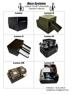
3 1.0 In t roduction The Lemur series printers are direct thermal ticket printers that may be purchased with o ptional integrat e d cutting mechanism and LCD display. This manual will provide the user with genera l information regarding printer set – up, configuration and troubleshooting. Please read the important safety information section before installation is cond ucted. Review t h e programming guide f o r additional details. 2.0 Unpacking the Printer The printer is shipped in a ruggedized container. Please save packing material for future use. Remove t he printer and a c cessories from the box and inspect for obvious damage. If damage is noticed, pleas e report it immediately to BOCA. Email: cathy@bocasystems.com Tel: (561) 998 – 9600 Fax: (561) 998 – 9609 The f ollowing items s h ould be in the box: a) Ticket Printer b) Hopper (if applicable) c) AC power cor d d) Interface cable (optional) e) Mounting Plate (optional) Above photo is of a Lemur – S printer. Lemur – S with top insert removed. Above photo of Lemur printer. Click here to return to > Table of Contents The shipping box and packagi n g material are specifically designed for y our printer. It i s rec omm ended you s ave the original box and packing material (includin g plastic bag if prin te r came with one) for future use, if needed.
PAGE – 5 ============
4 3 .0 Important Safety Information WARNING : The appearance of this symbol indicates the proximity of an exposed high voltage area. Please follow all dire ctions carefully for your personal safety. You must read the following safety information carefully before working on the printer. As a safety precaution, all service to the printer should be done by qualified persons with power off and the AC cord unpl ugged from the p r inter . Following any procedure requiring the removal of covers and/or doors, pleas e verify that they have been properly attached and fastened prior to operating the printer. WARNING: “Provide an earthing connection before the mains pl ug is connected t o the mains. And, when disconnecting the earthing connection, be sure to disconnect after pulling out the mains plug from the mains.” WARNING: Power Cord Set: This must be approved for the country where it is used: U.S.A. and Canada The cord set must be UL – approved and CSA certified. The minimum specification for the flexible cord is: N o. 18 AWG Type SV or SJ 3 – conductor The cord set must have a rated current capacity of at least 10A. The attachment plug must be an earth – grounding type wi th a NEMA 5 – 15P ( 15A, 125V) or NEMA 6 – 15P (15A, 250V) configuration. United Kingdom only The supply plug must comply with BS1363 (3 – pin 13 amp) and be fitted with a 5A fuse which complies with BS1362. The mains cord must be
PAGE – 6 ============
5 4. 0 Installation The Lemur seri e s printer was designed to be mounted either on a desktop or shelf (horizontal model) or vertically in a counter top (see Ap pendix B for in s tallation of vertical printers). Lemur – S model printer is not able to be mounted v e rtically. Prior to site preparation and installation, the printer should be powered up and run in the self – test mode. Lay the printer flat on a counter t op. On a Lemur – S model printer you will need to remove the side cover. Attach the AC cord and inte r face cable into the proper connectors. per. If you hav e a Lemur – R model printer please see section Appendix D L e mur – R Recommend that the stack of paper stock be fanned prior to use. This may be done by securely holding one side of the stack and fanning the other. You will want to do both sides. This fanning will help remove any paper dust or debris that may be o n the ticket stock, as well as reduce the paper dust in the printer too. Turn power on. The LCD will display PAPER OUT and the red CHECK PAPER led will be illuminated. Y o u will hear the cutter motor cycle if the printer contains a cutter. For Lemur – S p r inter you will need to remove the cover (see page 6 ). Begin loading tickets through the entrance slot with a smooth motion unt il the printer a u tomatically positions the ticket. See section 5.0 Ticket Load Procedure . NOTE: You want to make sure that the black timing mark is in the correct location before loading the tickets into th e paper path. S e e www.bocasystems.com / tickets_specs.html for black mark layout specs. After the ticket is automatically positioned (the green READY led will be illuminated), press the TEST b utton located on the control panel to print a test ticket. The next page shows sample self test tic k et printouts. Verify that the printer properly works with your system by issuing a ticket through your computer system. You may also use out customer – bas ed program to te s t the printer independently of your ticketing system (see Appendix F ) You may now install the printer in its permanent location. Adequate room should be provided behind the printer for the smooth feeding of ticket stock. Pl e ase do not prevent the ticket hopper (horizontal models) from operating by touching tickets during the printing cycle. Lemur , Lemur – R & Lemur – K cover removal T he printer is shipped there are two securing screws installed to hold t he cover in plac e . If the cover needs to be removed then it will be necessary to remove these (see p hoto latch (metal cabinet only) will ho ld the cover in p Same sc r ew on opposite si de too
PAGE – 9 ============
8 5.0 Ticket Load Procedure 1. Turn the printer on and wait five seconds. The red CHECK PAPER led will be illuminated (i f your printer has an o p tional LCD then it will display PAPER OUT ) . 2. Begin loading the tickets through th e entrance slot with a smooth motion until the ticket stock comes to a stop (at this point the stock is between the thermal head and platen ). Keep pressure against the sto c k and the printer will automatically feed the ticket stock. NOTE: see Appendix C for loading of Lemur – 2 and Lemur – 2K printers. If you have any ticket load issues then m ake sure the paper guild slider bar is properly adju s ted (see 9.1.6 Ticket Width Adjustment ). In October of 2019 B OCA transitioned over to using a Universal Paper Guide (UPG). Below are ph otos of said paper guide. If you have any ticket load issues then m ake sure the paper guild slider bar is properly adjusted (see 9.1.7 Ticket Width Adjustment ). Revers e Adjustable ( RADJW & RADJ4) Adjustable (ADJ4, ADJW & ADJ2 ) The black t i ming mark on the back of your ticket stoc k s h ould past over this si de facing d ow n towards the opto Load your stock towards thi s side and belo w this metal plate Load your stock b et w een two black entrance Adju stable (ADJ, ADJW & AD J2) Ticket Stock The black ti m i n g mark on the back of your ticket stock s hou l d past under t he si de with the do t and is facing down towards the bla ck mark sensor. Ticket Sto ck Rever se Adjustable (RADJW & RA DJ4)
PAGE – 10 ============
9 Above photo is of a plastic cabinet Lemur – S with optional cutter and cover rem oved . Your print e r may var y . Two typical ti cket formats and feed directions are shown below. The black timing mark must be facing the opto sensor . ck the black timi n g mark sh o uld be closest t o the leading edge of the ticket (the first part that goes into the printer).When loading 2 cinema ticket stock the black timing mark should be furthest away from to the leading edge of the ticket (the f irst part that go e s into th e printer). 6 .0 Configuration The Lemur series printer is factory configured for a variety of customer requirements. For a comparis on of the different electronics packages , refer to the B O CA System s website under the BASIC section. For a listing of configuration choices, refer to the BO CA Systems we b site und e r the SPECIFICATIONS section. Printers are configured with a reverse adjustable paper guide (RADJW) set to the customer specified wid th or optional adjustable paper guide (A DJ4, ADJW, ADJ2 & RADJ4). changing then the following will need to be done to ensure proper opera tion . 1. The paper path slider bar needs t o be adjusted fo r the widt h stock being used (see 9.1.6 Ticket Width Adjustment or 9.1.7 Ticket Width Adjustment for UPG printer ). 2. The SPECIAL HEAD setting needs to be changed to match the width s tock being used (see section Appendix A ) . For those printers wi t hout an LCD display see Appendix H . Adjustable (ADJ4, ADJW & ADJ2) paper path printer may leave the factory w ith the slider ba r set to its widest setting (AD paper path slider bar is properly adjusted for the width stock being used. (see section 9.1.6 Ticket Width Adjustment or 9.1.7 Ticket Width Adjustment for UPG printer ). Click here to return to > Table of Contents 3.25 or Black Ma rk Underside of Ticket Cinema T i cket Black Mark Undersi de of Ticket Standard Ticket Feed Direction
PAGE – 11 ============
10 7.0 Standard I n terface Pinouts RJ12 Serial Connection TYPICAL DB9 to RJ12 PIN C ONNECTIONS 9 pin host BOCA RJ12 2 2 Transmit 3 3 Receive 5 4 GND 6 1 RDY 8 6 CTS PARALLEL PIN FUNCTION 1 Strobe (negative) 2 – 9 Data (DB0 – DB7) 10 ACK (negative) 11 BUSY 12 PAPER OUT 13 SELECT (negative) 15 ERROR (negative) 18 Gr ound USB Print e rs prior to serial number 271200 are USB 1.1 compliant devices. Printers after serial number 271200 are U SB 2.0 compliant devices. ETHERNET (Optional) is a standard RJ4 5 Ethernet cable connection. WI – FI (Optional) is comp atible with 802.1 1 b /g Wi – Fi router and supports security settings WEP/WPA/WPA – 2. Printers built after July 2020 (s/n 452607 and hi gher) are able to support 802.11b/g/n Wi – Fi router. BLUETOOTH (Optional) Allows connection via Bluetooth interfac e. NOTE : The a bove pinouts may vary on certain printe r s due to special customer request. Click here to return to > Table of Contents +5VDC RJ12 Con nec t or USB RJ12 s eria l Ethernet (O ptional)
245 KB – 65 Pages