Immediately turn off the VASTEX Conveyor Curing System if products become jammed in the drying chamber or conveyor belt. • Do not remove any cover or guard
149 KB – 20 Pages
PAGE – 1 ============
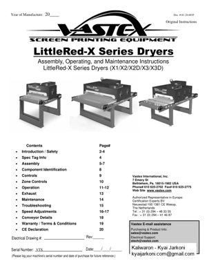
LittleRed-X Series Dryers Assembly, Operating, and Maintenance Instructions LittleRed-X Series Dryers (X1/X2/X2D/X3/X3D) Serial Number: (Please log your machine’s serial number and date of purchase for future reference.) Date:____/____/______ Electrical Drawing #: Rev:______ Doc. # 01-28-001F VTX Vastex E-mail assistance Purchasing & Product Info: sales@vastex.com Electrical Support: stech@vastex.com Tech Support, Mechanical Setup, and Operation: techsupport@vastex.com Original Instructions Vastex International, Inc. 7 Emery St Bethlehem, Pa. 18015-1982 USA Phone# 610 625-2702 Fax# 610 625-2775 Web Site www.vastex.com Authorized Representative in Europe: Certification Experts BV Nieuwstad 100 1381 CE Weesp, The Netherlands Tel : + 31 (0) 294 Œ 48 33 55 Fax : + 31 (0) 294 Œ 41 46 87 Year of Manufacture: 20____ Contents Page# Introduction / Safety2-4Spec Tag Info4Assembly 5-7Component Identification8Controls9 Zone Controls10Operation11-12 Exhaust13Maintenance14Troubleshooting15Speed Adjustments16-17Conveyo r Details18Warranty / Terms & Conditions19CE Declarat ion20
PAGE – 2 ============
The Instruction Manual and Safety Instructi ons must be read and understood by anyone operating the Vastex Conveyor Curing System. The operator should read and understand the instruction manual before operating this equipment. Store instruc- tion manual and safety instructions near equipment for easy access to operators. VASTEX Conveyor Curing System is intended for the curing of non-flammable inks on screen printed materials. Do not use for any other purpose unless authorized by Va stex International, Inc. Use of this equipment for any other purpose can be dangerous and may cause damage to this equipment, voiding the warranty. It is recommended that the area around this equipment be designated as a work area and only authorized em- ployees be allowed in the area. Children and pets must be kept clear of the work area. Do not place any objects on top of the drying chamber. Surfaces are hot! Never leave equipment unattended. Do not operate conveyor or dryer with any cover or guard removed. Operator must be familiar with controls of the drye r and conveyor. Never put excessive load on the conveyor belt. Before starting production, the operator must check that all covers and guards are in place, no material has been left on the conveyor, and the work ar ea is clear of obstructions. Switch on and verify conveyor belt is moving before turning on the heat. Allow dryer to cool to 300°F (149°C) before switching off conveyor. Always turn off power at the main disconnect at the end of production. In case an abnormal symptom occurs, for example excessive vibration, noise, and strong smell or smoke devel- opment, turn off the VASTEX Conveyor Curing System and contact a qualified technician. Immediately turn off the VASTEX Conveyor Curing System if products become jammed in the drying chamber or conveyor belt. Do not remove any cover or guard until power at the ma in disconnect is switched off and locked out. No unau- thorized persons are to be allowed inside the control boxes. Turn off and lock out power at the main disconnect before any cleaning or maintenance. Only qualified technicians should be allowed to ma ke repairs on the VASTEX Conveyor Curing System. Noise and vibration: This equipment does not produce noise exceeding 70 dB(A) at workstations. Operating Temperature: Vastex Equipment should not be operated in temperatures below 40°F(5°C) or above 105°F(41°C) Congratulations, you have chosen a VASTEX conv eyor curing system. VASTEX has been designing and building dryers since 1960 and has the knowledge and expertise to supply a quality dryer and help you keep it running for years to come. VASTEX has innovated many of the features found in conveyor ovens today from control methods, modular features, air movements and belt tracking. Your Vastex Infrared Dryer has been Factory tested and burned in for a period of 2-8 hours. All components are tested to be sure they work correctly when the Dryer leaves our factory. Introduction Safety
PAGE – 3 ============
Stability during use, transportation, assembly, dism antling when out of service, testing, and fore- seeable breakdowns: This equipment is designed and expected to be stable during all foreseeable con- ditions, so long as the procedures and instruct ions given in this manual are followed. Safe handling, transport, and storage: Before storing the unit, follow the shutdown procedure on P. 9 (or on the front of your machine) to allow the heater assembly to cool properly. No special handling con- siderations are necessary, except to be aware of t he weight of the equipment and take standard precau- tions for moving such weights: LittleRed-X1-30: 172 lbs (78 kg), 47.5fl x 40.3fl x 46fl (121 cm x 102 cm x 117 cm) LittleRed-X1-54: 380 lbs (172 kg), 65.5fl x 65fl x 50fl (166 cm x 165 cm x 127 cm) LittleRed-X2-30: 304 lbs (138 kg), 83.5fl x 40.3fl x 48fl (212 cm x 102 cm x 122 cm) LittleRed-X2-54: 480 lbs (218 kg), 83.5fl x 65fl x 50fl (212 cm x 165 cm x 127 cm) LittleRed-X2D-30: 304 lbs (138 kg), 65.5fl x 40.3fl x 50fl (166 cm x 102 cm x 127 cm) LittleRed-X2D-54: 480 lbs (218 kg), 65.5fl x 65fl x 50fl (166 cm x 165 cm x 127 cm) LittleRed-X3-30: 420 lb (191 kg), 87.5fl x 40.3 x 50fl (222 cm x 102 cm x 127 cm) LittleRed-X3-54: 700 lb (318 kg), 87.5fl x 65 x 50fl (222 cm x 165 cm x 127 cm) LittleRed-X3D-30: 420 lb (191 kg), 87.5fl x 40.3 x 50fl (222 cm x 102 cm x 127 cm) LittleRed-X3D-54: 700 lb (318 kg), 87.5fl x 65 x 50fl (222 cm x 165 cm x 127 cm) Please read and understand all parts of this manual to avoid any Residual Risks. Loose or dangling clothing may become entangled in the pulley. The pulleys are guarded against direct contact. Your Vastex Infrared Dryer has high temperature heater s. There is an inherent danger when dealing with a heat source of this degree. These heaters are often run at temperatures near 1,000° F(538° C). Any body part or item that comes in direct contact with the heaters will be damaged. The heaters are guarded against direct contact from all sides except the bottom. The workspace that your Vastex Infrared Dryer oc cupies must be kept clean and clear of debris. All sides of dryer must be reasonabl y accessible by the operator. A clear perimeter of 18fl is preferred. Do not store items, especially food or drink, on the top of your Vastex Infrared Dryer. The room that you are operating your dryer in should be adequately ventilated. Please re fer to the MSDS sheet of the ink you are curing. Safety (cont™d) Residual Risks Workspace
PAGE – 4 ============
*** REMOVE THE CLEAR HEATER / SENSOR PROTECTO R SHEET BEFORE OPERATING THE DRYER *** (protector sheet is located between t he heater face and the sensor bracket) At the end of all shifts and / or production runs, follow t he Dryer Shutdown Procedure posted on the front of the dryer. Any restriction in the dryer exhaust may result in excessive heat buildup within the chamber. Follow the Dryer & Exhaust Hood Ducting directions in the manual. Placing your equipment into service and using your machine: To place your machine into service, follow steps 1-9 on pages 5 through 7. To use your machine, follow the instructions on pages 11 and 12 , after familiarizing yourself with the controls of your ma- chine (see pages 9 and 10). Vastex Model # Input Voltage Rated Amp Draw Heater output Single or 3 Phase Weight of Machine Year of Manufacture Important Spec Tag
PAGE – 5 ============
Tools Needed : (2) 9/16fl open end wrenches, (1) 7/16fl open end wrench or so cket, (1) 1/4fl nut driver OR flat blade screw driver 2) The belt needs to be installed as shown in the diagram. To connect your belt, align the Alligator Lace and install the pin. Aligner 3) The belt needs to be tightened and ad- justed. To tighten and adjust the belt, use the Aligner Bolts. To raise the Aligner, turn the Aligner Bolt clockwise with a 7/16fl wrench. To lower it, turn it counter clockwise. Raise the Aligner until you have about 2fl-2½fl of slack as shown on right. Additional details on PAGE 7. Aligner Bolt Belt Travel Front Pulley Rear Pulley Alligator lace 1) Each conveyor has a pair of legs, a Front section, Rear Section, and middle conveyor pieces. Bolt together each section, as shown in the diagrams. Refer to Page 18 for each conveyor™s specific layout. All parts are attached together using 3/8-16 x 3/4fl bolts and 3/8fl Serrated locknuts. Assemble the Front Section, Rear Section, and mid- dle conveyor pieces first. Place assembled conveyor onto legs, attach using 3/8-16 x 3/4fl Bolts and 3/8fl Locknuts Tighten all with 9/16fl open end or socket. Front Section Drive Section Assembly Middle Section
PAGE – 6 ============
4) Install the chain guard with the (2) black #8 machine screws. Tighten with 1/4fl nut driver. See Maintenance section for chain adjust- ment 5) Install the (3) Belt covers. Each uses (2) black #8 Screws. Tighten with 1/4fl nut driver. Do not operate with Chain Guard removed. Serious Injury may result! 6) Place the Heat Chamber on the conveyor, centered between the belt™s rollers, wi th the Control Panel on the right side. 7) Electrical Connections Route the Conveyor Motor wire (the smaller wire coming from the control box) along the bottom of the conveyor side as shown. P clips are provided to manage the wire along the con- veyor. Connect the threaded cpc connection to the motor plate. LR-X1-30 only: Connect the Machine Plug to an appropriate outlet. (ALL OTHER MODELS): Your machine is a hardwire installation provided by the end user™s qualified electrician. See Electrical Drawing for electrical require- ments. Many variations available. If the incoming power comes from the ceiling, remove the Wire Clips using a 1/4fl nut driver, and separate the power wire from the Motor Wire. Reinstall the Wire Clips with just the Mo- tor Wire routed through them. Chain Guard Belt Cover #8 Machine Screws Heat Chamber Motor Plate Threaded CPC connection Machine Power Wire8) Ducting LittleRed Dryers with powered exhausts come with a repositionable elbow. Be sure to adjust this to suit your shop™s requirements and restrictions. A 10% reduction of airflow is permitted due to customer added ducting. The output of the exhaust fan is 177CFM for X1/X2-30 models, and 380CFM for all 54fl models with exhaust and X3D-30. If cus- tomer added ducting decreases flow by more than 10%, a duct fan MUST be added. Please Contact Vastex or refer to document 01-15-003C for additional Ducting information. Assembly (cont™d)
PAGE – 8 ============
Conveyor Components IR Heater- w/ J Sensor Gear Motor Belt Belt Aligner Front Pulley Belt The conveyor belt is made of Teflon coated fiberglass. It is joined together with an alligator lace using a steel pin to connect each side. The belt will not burn under normal conditi ons but the dryer should always have t he belt moving while the heaters are above 300 °F(149° C). The belt should remain tracked in the center of each pulle y. (See fiBelt Installation and Trackingfl for adjustment instructi ons.) Aligner The aligner is a device for tracking the belt and keeping it on t he pulley. As the belt moves from side to side the aligner is used for ad-justments to keep it centered. The belt does not have to be perfe ctly centered on the pulley but should not be hanging over eit her edge. LittleRed-X1 and X2 come standard with an aligner roller. Pulley The pulleys at either end of the conveyor are made by VASTEX of 4 ½ inch tubing with ¾ inch center shaft. They are mounted on self aligning flange bearing blocks for precision rolling. Gear Motor A 90 or 130 Volt DC gear motor is located to the rear of the conveyor. It drives the rear pulley and belt with a roller and a # 25chain(standard drive) or #35chain(HD dr ive). Replacement part numbers c an be found on the wiring diagram. IR Heater The infrared heaters in VASTEX dryers emit m edium wave infrared heat, perfect for curing many types of inks. The heater connect ions are located in the trough on the right side of the heater, connect ed with high temperature terminals and stainless steel socket head cap screws. (See Wiring Diagrams for Heater Specs) J Sensor The sensor is mounted under the heating elem ent, on the side closer to the control panel, with a shield beneath it. On X2 model s, the sensor is on the rear heater. The sensor is wired to the temperature controller using two wires, a red (positive) and a white ( negative). They must be attached to the proper terminals on the cont roller. Refer to wiring diagra m when replacing fiJfl Sensor. (if SBER is dis-played on controller fiJfl S ensor is malfunctioning) Control Box The Control Box houses all the electrical components of the Dryer except the Drive motor. More information on the Control Box a nd Control Panel found in section Controls. Exhaust Stack (Optional) 3fl exhaust stack on X1/X2 30fl models, 4fl exhaust stack on X1/X2 54fl and 30fl X3D models. 5fl exhaust stack on X3D-54. Powered exhaust removes fumes/moisture from the cham ber. See Dryer & Exhaust Hood Ducting for proper venting. Pow-ered exhaust is standard on LittleRed-X2 and X3 models and Optional on LittleRed-X1 Chamber Components Control Box Powered Exhaust Stack Rear Pulley (LR-X2-30 Shown) Component Identification
PAGE – 9 ============
DC Volt Meter: Digital Volt Meter displays, in volts, the amount of power going to the belt motor. A table show- ing the time associated with voltage can be found in Dryer Operation. Belt Speed Control: An AC-DC converter, mounted to the face of the control panel, allows the operator to vary the belt speed / DC volts to the motor. The dial is for reference only and does not represent seconds in the heat. Control Output Light: This light should cycle on & off with the controller, indicating output signal to relay. System Switch: Sends power to Controls. Shut off power at main disconnect before servicing, Power Light must be out before entering any part of this machine Power Light: It is wired to the line cord and/or the Shut Off Switch and will be illuminated whenever power is coming into the unit. At the end of the day, the machine should be disconnected so this light is out. Temperature Control: See Dryer Operation for more information Heat Switch: Controls power to heater only. Relay Output Light: This 250 volt RED pilot light is wired to the output side of the relay. This light will cycle on & off with the control output light. It verifies that the relay is working properly. Controls Shut Off Switch Machines that are direct wired by the end user are equipped with a shutoff switch. This is the main junction block for incoming power, and is used to restrict access to the control box while it is live. The shutoff must be in the OFF position to enter the control box. START Controls (LittleRed-X2D/X3D) Controls between all LittleRed-X Models are si milar. Refer above for all unlisted controls. BOOST Zone Temp Control: Controls Temperature of Boost Zone. Must be set to the same temperature OR HIGHER than the MAIN Temperature control. MAIN Temp Control: Controls Temperature of MAIN heat zone. BOOST Heat Switch: Controls power to BOOST zone only. MAIN Heat Switch: Controls power to MAIN zone only. Shut Off Switch: LittleRed X2/X3 2 Zone Control: LittleRed X2 models are equipped with a 2 zone control. Each zone has an independent Heater and Relay light. Addt™l info found on Page 10 Front Zone Rear Zone
PAGE – 10 ============
Zone fiRearfl Zone fiRearfl on your LittleRed-X2 is the rear heater. Zone fiRear on your LittleRed-X3 is the middle and rear heaters. On the c ontrol panel, Zone fiRearfl heat is turned on and off with the BOTTOM toggle switch labeled fiRearfl. When operating your LittleRed, Zone fiRearfl must be used. Zone fiRearfl has the temperature sensor attached to it, and controls the heat for both heaters. Use only zone fiRearfl if you are running the dryer slower, and want to conserve on energy costs. Zone fiFrontfl Zone fiFrontfl on your LittleRed-X2 is the Fron t Heater. On the control panel, Zone fiFrontfl heat is turned on with the TOP toggle switch labeled fiFrontfl. The Relay and Heater lights next to the fiFrontfl switch show its operation. The temperature control measures the heat under Zone fiRearfl only. Zone fiRearfl MUST be on to run zone fiFrontfl Zone fiFrontfl requires an average of 15 minutes to heat up to 750°F (400 °C) . Zone Control X2/X3 Zone Control X2D/X3D Zone fiBOOSTfl Zone fiBOOSTfl on your LittleRed X2D or X3D is controlled indepen dently. This Zone is used to superheat your garments on the way into the chamber. Typically, the lo nger your garment is in the chamber, the lower this BOOST zone can be set. Setting the BOOST to 1100F+ is recommended for cure times at or below 60 seconds. Setting the BOOST to 800F+ is recommended for cure times between 2 and 4 minutes Zone fiMAINfl Zone fiMAINfl on your LittleRed X2D or X3D is controlled ind ependently. This Zone encompasses 85%(X2D) or 90%(X3D) of your cure time. If you are running plastisol or other non-specia lty items, you may set the BOOST and MAIN zones to the same temp. The dryer will perform similar to other infrared dryers when BOOST and MAIN zones are set the same. Setting the MAIN to 650F + is recommended fo r cure times at or below 60 seconds. Setting the MAIN to 500F + is recommended for cure times between 2 and 4 minutes BOOST ZONE CONTROL BOOST ZONE DIAGNOSTICS MAIN ZONE DIAGNOSTICS MAIN ZONE CONTROL
PAGE – 11 ============
Set the Belt Speed : Rotate the Belt Speed Control Knob clockwise to increase speed and counter-clockwise to decrease it. Refer to the charts on the next page for fiTime Through Chamberfl settings. For Plastisol inks, a good starting point is 20-25 seconds in the chamber. Set the temperature: With the power on, push and hold the up arrow, th e (SV) will climb. The longer you hold the button, the faster the (SV) will climb, it will start climbing by one, then ten, then hundreds. Set the desired temperature and allow approximat ely 15 minutes for heat up. Refer to the trouble shooting section for Controller Error Messages. Curing Plastisol with infrared: Plastisol ink can fully cure in approximately 20-30* seconds. T he ink must achieve 310°-320° F (154°-160°C) to cure and fuse t o the garment. We recommend* a starting temperature 800°F (400 °C) , 3fl heater height, and 25 seconds in the chamber. Discharge or water based: Water based products require more time than plastisol to cure due to the fact that the water/moisture must be evaporated befor e the ink can cure. We have seen cure times from 50 to 90* seco nds to achieve a full cure or discharge and not damage the gar- ment. Please note as the time is increased the temperatur e must be decreased to protect the garment from scorching. *Actual cure times can vary depending on conditions such as garment moisture an d color, ink color, ink thickness, and environmental conditions. All three variables should be used to maximize production while insuring a proper cure. How to determine Temperature set point: The sensor is located directly under the heater so it will read a much higher tem perature than seen at the garment. Set the te m-perature several hundred degrees higher to compensate for this difference. A non contact heat gun can be used to read the temperature of the ink at the e nd of the dryer while it is still under the last heater. Take into consideration the thickness o f the ink when using the heat gun. It will measure the top layer of the ink. If the ink is very thick you must add a buffer to be sure cure temperature is reached throughout the ink. Temperature set point, heater distance to the garment, and belt speed will all effec t the ink temp. Turn on Heat Switch : Turn on the temperature controller and set desired temperature. Set the Heater Height : Using the knobs on the side of the dryer, Raise or lower each side of the heater(s) to desired height. Loosen the knob, raise or lower it to the desired height, then tighten. Use the individually height adjustable haters to tune in your required heat profile. Main Disconnect : Turn on System Switch : Power is sent to the heater switch, belt speed control and the powered exhaust blower turns on. Turn on Conveyor : Set speed to desired setting. Check belt path: Remove any objects from the conveyor and belt. Turn on Power on The red Power Light will illuminate. The LittleRed should be wired to a Main Power Disconnect. (Optional) Disconnect bracket available. Control System Summary: The control system in your dryer is called a ficlosed loop sy stemfl. The system includes a Digital Controller mounted to the control panel, a Sensor mounted in a shield under the heater, a relay and an Infrared Heater. The digital controller is set to the desired temperature and the Sensor measures the temperature at the face of the heater. The sensor re- ports back to the control, and the relay sw itches the heat on and off to the heater. Startup Procedure Dryer Operation
149 KB – 20 Pages