by D Hansel · Cited by 12 — The list of blast cleaning possibilities is endless. With the vast available range of abrasives and media, and various types of process equipment, there is the
281 KB – 24 Pages
PAGE – 1 ============
Q* F% ABRASIVE BLASTING SYSTEMS d g by Dave Hansel Clemco Industries Corp., Burlingame, Calif. Abrasive blasting requires various essential equipment elements for productive cleaning 1; mating of metal surfaces. The blasting process involves projecting abrasive particles using ,:;lllpressed air as the source of power. Successfuily converting compressed air and motionless abrasive particIes into an effective cleaning treatment takes a combination of common sense and engineered components. Each element in an abrasive blasting system is a major contributor to the overall performance of the system. If one element is faulty, for whatever reason, the entire system will fail to fulfill its expected level of achievement. The abrasive blasting process is well known for outside cleaning of bridges, ships, and other steel substrates. It is, however, a highly productive method of cleaning and treating metal surfaces in enclosed systems. Enclosed systems range from manually operated cabinets. where the operator is positioned outside of the blast chamber. to large rooms where one or more operators work inside the enclosures. Within this range, enclosed systems offer countless mions of standard and custom-designed automated features tailored to production and – ..:irnent requirements. Whether work is performed inside or outside. manually or automated. \.-,sang productivity is determined by the selection and use of effect~vs components. APPLICATIONS A wide range of applications exists for abrasive blasting. Although the most familiar are blasting steel bridges and concrete buildings, there are many other common blasting processes that improve the appearance of parts, remove unwanted flashing and buns, or add strength to high-stress rr?ater%s. Thee of the more prevalent applications are described below. Surface Preparation This application category encompasses the process of preparing surfaces for coating materials. Widely known is bIast cleaning of steel to remove old paint, rust, and other contaminants, or, if it is new steel, removing mill scale that has formed on the steel surface . . dumg the manufacruring process. The second major function when blasting steel is producing a surface profile. Profile, which is also called “etch” or “roughness,” is the texture resulting from impact of abrasive particles on the surface. Coating manufacturers generally specify the type of profile required to ensure that their coating material will perform as designed. Surface preparation applications are not restricted to steel and masonry. Fiberglass materials are blasted to remove the top layer of glaze (gelcoat) and expose air bubbles. Aluminum, titanium, magnesium, and other sophisticated metals require elimination of corrosive matter and, if they are to be coated, a surface profile. Highly advanced materials, such as composites used in aircraft and aerospace industries, are blasted with the newer, less aggressive, abrasive media. Airplanes, helicopters, car bodies, trucks, and boats are stripped of their deteriorating paint by blasting with piastic, wheat starch, and agricultural media at low air pressures. The list of blast cleaning possibilities is endless. With the vast available range of abrasives and media, and various types of process equipment, there is the potential that the surface preparation on most materials can be accomplished by abrasive Hasting. Surface Finishing Surface finishing differs from surface preparation in that the desired result of abrasive blasting is to improve the appearance and utilization of a product, rather than condition it for
PAGE – 2 ============
coating. Typical surface finishing processes are deflashing and deburring of mold-formed parts, removal of production contaminants, and enhancement of visual features. Primary users of abrasive blasting are metal foundries where parts are produced by sand casting, permanent mold casting, and die casting. Cast parts almost always have small burrs, which must be removed for functional and aesthetic purposes. An added benefit of blasting cast parts is the ability to reveal minute cracks and defects that are not readily visible. This advantage is especially important to aircraft repair facilities that recondition airplane wheels. Softer molded materials, such as rubber and plastics, usually emerge from molds with flashings caused by tooling separation. In many cases, flashings can be quickly trimmed off by abrasive blasting, leaving a smooth. uniform finish. There is an enormous market for abrasive blasting in industries that use heat treating as a hardening process. Heat treating requires tremendously high temperatures, which normally create discoloration of parts. Blast cleaning these parts with various types of blast media easily removes discoloration and any heat-treat scale, which also may have formed. Another common purpose of abrasive blasting is to improve the appearance of a product. Several types of abrasive and media are used to remove stains, manufacturing compound residue, corrosion, and tool marks. Some media can blend visual surface variations into an overall uniform appearance. This is especially true on parts with scratches and cuts caused by tooling fixtures. High operating temperatures and hot lubricants cause buildup of carbon and burnt oil on many automotive parts. Electric motors become clogged with overheated insulation and melted motor stator lamination. In most cases, retaining original dimensions of a part is critical. Use of abrasive and media that do not affect tolerances. such as plastlc media. glass beads, and agricultural abrasive. allows the integrity of the part to be maintained while removing unwanted contaminants and providing an acceptable cosmetic effect. Surface Campression Compressing a surface by abrasive blasting is a specialized field that has become essential to the life of high-stress components. The compressing technique by abrasive blasting is called “shot peening.” Increased fatigue strength of metal surfaces is achieved by bombarding the surface with a high-velocity stream of preselected round balls. Steel shot, ceramic shot, and glass beads are prominent media used in the shot peening process. Peening gives the effect of stretching and compressing the surface, thereby reducing operational stress. As a result, a shot-peened part is more durable than its original form. Shot peening is a rather precise science, as underpeening and overpeening may cause early failure of a given part. Exacting specifications are written and must be followed in most applications. Two major users of shot peening are the automotive and aircraft industries. Gear manufacturers use peening to eliminate burrs and sharp edges, as well as to add strength to gear teeth. Spring manufacturers use shot peening extensively to combat stress tension throughout their products. Another popular use of shot peening is on metal castings and forgings. In these cases, there are multiple benefits of the peening process. Shot peening provides part cleaning, elimination of porosity, exposure of defects, and improvement in appearance. Many threaded parts incorporate the peening process to remove sharp edges while increasing thread holding power. STEEL SURFACE PREPARATION SPECIFICATIONS There are two highly important requirements in preparing steel surfaces for painting; one is suvace profile and the other is degrees of cieanliness. Both are critical to the performance of any coating system, especially with the advanced, long-life formulations used in coatings today.
PAGE – 3 ============
Coating manufacturers have long recognized the necessity of proper surface preparation i, if their coatings are to succeed as they have claimed. Improperly cleaned steel surfaces will ,. cause costly premature failure of the coating; consequently, coating manufacturers specify I , how the surface is to be cleaned and textured prior to applying their products. Failure to follow li it specifications results in denial of coating performance guarantee. I Surface Profiie Considerable research has been conducted by coating manufacturers and professional – organizations on surface profiles required for various paint systems under a wide range of environmental conditions. Studies have found that certain types of coatings require speclfrc profiles to ensure adhesion and complete protection of the substrate. Profiles provide a mechanical method of positive. uniform bonding of the coating, allowing the coating to last as long as stated by the manufacturers. Profile, which is sometimes called “etch” or “roughness,” is produced by abrasive particles propelled by compressed air at high velocity from an abrasive blast nozzle against a surface. Abrasive particles cut into the steel to form countless peaks and valleys. The resultant contour provides a surface on which the applied coating can obtain a tight &grip. Sophisticated coatings simply will not adhere to flat. smooth surfaces because there is nothing for the coating to grasp Depth of profile is controlled by the size, type, and hardness of abrasive. and by the pressure. surface distance, and impact angle of the blast nozzle. Different abrasives cresre different profiles; therefore. selection of the abrasive is extremely important in complyins with specifications. Profiles are measured in mils or microns. A mil is 1/1,000 of an inch. A micron is 1/35 of a mil (i.e., 25 microns equal 1 mil). The most common term used in the United States is mil, which is used to measure paint thickness. as well as surface etch. Typically, specifications state a mil profile height average due to the wide range – of abrasive partic!e sizes wi~hn s given abrasive suppiy. For example, an average profile of 2 mils (50 microns) may actually show a mixture of profiles as small as 1 mil (25 microns) and as large as 3 mils (75 micronsL Precise profiles are simply not possible because there is no practical method of producing exact abrasive particle sizes. Once the abrasive has been selected, it is important to establish strict blasting techniques. Any deviation in nozzle air pressure, nozzle distance from the surface, or angle of abrasive impact will affect profile results. Reduction of air pressure or increased nozzle distance may cause smaller profiles. Severe nozzle angles may produce a skimmed blast pattern, rather than definite peak and valley projections of a profile. For best results, nozzles should be positioned to blast at 80-90″ to the surface and at a distance where abrasive speed reaches its optimum acceleration. There are various types of instruments for measuring profiles. It is essentiai to utilize a measuring device to check and document profile conformance. Careful monitoring of the profiles will prevent expensive rework (see Fig. 1). Degrees of Cleanliness Proper blast cleaning of steel surfaces is an absolute necessity prior to applying coatings. It is no mystery that paint will not last long on a dirty, rusted, or contaminated steel surface. New steeI must also be blast cleaned to remove mill scale, as mill scaie will loosen in time and cause premature paint failure. Depending on the coating and type of service to which the steel product is subjected, four grades of cleanliness have been established by professional industrial organizations. The four grades are classified as degrees of cleanliness, which range from 100% removal of all contaminants to a quick blast to remove only loose materials. The four degrees are white metal blast, near white metal blast, commercial blast, and brush-off blast. Several pages of the Steel
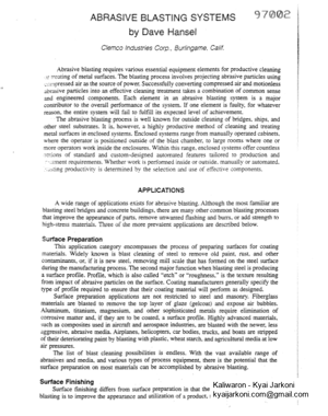
PAGE – 4 ============
Coating Profile Substrate Fig. I. When surface profiles uceed the musinzum specifkatiot~s. the peaks may protrude :/~t-cm~qh the coating system. carisiilg it ro fail. Sir~ctures Painting Council’s (SSPC) Systems c1r7d Specij2cariotzs ;Llunrml are devoted to describing each degree of clemliness. but a brief definition follows. Wlzire metal hlusr: Removal of all visible rust. mill scale. paint. and foreign matter. This level of cleanliness is usually required where sophisticated paints. such as zinc-rich coatings, are applied to materials that are located in highly corrosive areas. Typical applications are salt water bridges. chemical plants. and offshore drilling rigs. Near white metal blast: Blast cleaning until at least 95% of the surface area is free of all visible residue. Very similar to white metai, but allowing for some slight staining on the metal. This degree of cleaning is required for high-performance coatings where the-steel is exposed to harsh elements and heavy usage, Commercial blast: Blast cleaning until at least two-thirds of the surface is free of all 7.,i..;!ble residue. For most applications where standard coatings are applied, commercial blast is specified. It primarily allows tightly adhering old paint to remain on the surface because of the contention that if the old paint is still good, why remove it. Brush-off blast: Blast cleaning of all except tightly adhering residues of mill scale, rust, and coatings, exposing numerous evenly distributed flecks of underlying metal. This cleaning method is acceptable for materials that are not subjected to severe environments or where long-term coating life is not expected. Complementing the written definitions of degrees of cleanliness are several visual comparators produced by professional organizations. The SSPC has produced a set of photographs in a pocket booklet form that shows the c1eanliness grades on four types of surface conditions. The four conditions cover steel surfaces with mill scale, mill scale and rust, total rusting, and rust with pitting. The National Association of Corrosion Engineers INACE) developed a set of encapsulated steel coupons that simulate the four degrees of cleanliness. For reference, the four degrees of cleanliness standards are shown in Table I. Abrasive blasting should be attempted only by trained and experienced personnel knowledgeable in the standards of surface preparation. Advancements in the quality and longevity of paints developed by coating manufacturers dictate the need for perfection in surface preparation. BLASTING PRINCIPLES There are two operating principles of blasting-suction blast and pressure blast. suction machines are usually small pieces of equipment primarily designed for light duty work or
PAGE – 5 ============
Table I. Standards for Cleanliness minor cleaning applications. The most common use of the suction principle is in blast cabinets where work areas are lim~ted and blasting requirements are less aggressive. Pressure blast I i machines are also used w~th cab~nets for tough cleaning jobs. Pressure blasting is utilized in I blast room applications. Suction (sometimes called “venturi”i uses a method of drawing abrasive from a nonpressurized container into a gun chamber and propelling abrasive panlcles out of a nozzle. Typically, a suctlon system con\t\rs of a blast gun. two horsb-onc for air and one for abrasive-and an abrasive cont:imer. The blast gun tias a nozzle. alr jet. gun body, and hose connections (see Fig. 2). By mounting an air jet in line and behlnd .i nozzle. compressed air Fig. 2. Suction-ype hhsr gun.
PAGE – 6 ============
flowing through the gun body from the air jet will develop a drawing actlon. This brings abrasive up through the abrasive hose into the gun body. where it is accelerated through the nozzle. Suction biasting yields one-fourth to one-third the velocity and surface impact of pressure blasting. Consequently, suction blasting is more appropriate for light to moderate applications. More popular uses center around soft sophisticated merals where mild debumng, light shot peening, and thin scale removal are required without deep penetration of the base metal. As a typical example. aluminum, titanium. and magnesium automotive and aircraft parts are suction blasted. Pressure b!zsx systems are easiiy distinguishabie from suction types by the use of one ‘lose, as opposed to two hoses. to feed the nozzle. Air and abrasive travel through a single blast nose at high air pressure and rapid speed, resulting in intense surface impact. VENTILATED ENCLOSURES A wide variety of abrasive blasting enclosures are available to accommodate part sizes, cleaning or treatment requirements, production rates, and budgets. Blast enclosure methods include airless blasting (centrifugal wheels), water blasting. and dry air blasting. This article focuses on dry air blasting enclosures and equipment. Blast Cabinets Air-blast enclosures start with simple, manually operated blast cabinets (see Fig. 3). These cabinets range in standard sizes from 24-in. wide by 24-in. long (600 X 600 mm) to 72-in. wide by 72-in. long (1,800 X 1,800 rnrn). Typically, they are equipped with one operator station, which includes a sealed pair of gloves, a wide viewing window, and lights. Inexpensive, light duty cabinets are equipped only with dust collectors. They do not have media cleaning or efficient screening components. Generally, light duty cabinets are used for infrequent blasting applications where cleaning the media after each blast cycle is not a necessity. Applications where a cabinet may be used more than an hour per day, and when reuse of contaminated media is not acceptable, require abrasive reclaimer/screening equip- ment.
PAGE – 8 ============
Oscillating pans are supplied at various lengths in 3-, 4-. or 5-t’t (900, 1,200. or 1,500 mm) wide section5 stet4 pan in each section is tiiing by iink chain and is oscillated back and forth by eccentric cams. A central screw conveyor collects and delivers abrasive from the ?us to an outside bucket elevator. Abrasive is cleaned and stored in an abrasive cleaner as .!scribed in the wiper vane system. A single small electric motor operates all the cams in an average-size floor. This system is designed to handle coarse. anpiar abrasive. It is available for partiai floor recovery areas at any combination of width sizes to tlccornmodate economic limitations. The screw conveyor system’s primary advanta,oes are abrasive recovery volume, speed, and distance. On long length blast rooms [over 50 feet (13 meters)]. a screw conveyor will move greater amounts of abrasive faster than by other methods. This system consists of rows of motor-driven screw augers mounted in steel troughs, covered with steel grating. The floor augers connect to a cross collection auger. which takes abrasive to the inlet of a bucket ‘ elevator. The bucket elevator, abrasive cleaner, and blast machine are the same equipment as used with the other mechanical recovery systems previously described. The versatility of this \)istern allows any number of screw conveyor sections to be placed anywhere in the floor area. Blast Room Parts Handling Options Materials may be brousht into blast rooms by many different methods. Hand trucks and small wheeled carts are used to handle lightweight parts. Heavier parts are transported by forklift trucks. There are, however. several options available to reduce handling time and increase production. One common option is a monorail mounted on the biast room ceiling, using a pneumatic or electric hoist to lift, cany, and place parts. Another popular option is steel-decked work cars riding on rubber-tired wheels or steel shells. The steel wheels are often the flanged railroad type of wheei, which allows them to be
PAGE – 9 ============
used with rail tracks. Work car wheels may be driven by pneumatic or electric motors, i although a more common method is to use motor-powered steel cables to pull the carts in and 1 I out of the room. I There are many other material handling methods designed of specific parts ru~ be I i j processed through the room. A few examples are steel roller conveyors, rubber belt conveprs, i’ “cherry picker” hoists, cranes, and large turntables. The choice of parts handling is prediuted : i :I on desired production speed and cost justification. .I 7 – Pneumatic Reclaimers Pneumatic abrasive reclaimers provide one of the best methods of removing dusr and large contaminants from recycled media. Reclaimers, sometimes referred to as cycfone separators, work on the principle of centrifugal force to spin media at a rapid rate to sep;mte heavy particles from light particles. Media are drawn up through vacuum hoses from the bottom of cabinets by means of electrically powered irnpellors. The media-spinning axion begins as soon as the media enters the reclaimer. Heavier particles and debris are thrown to the outer perimeter of the reclaimer while lightweight dust particles circle around the reclaimer center, where a suction tube connected to the dust collector pulls the dust out. MELVy reusable particles and debris swirl downward into a meshed screen. The screen captures &&-is and allows heavy media to pass through to a storage area for reuse. There are two basic reclaimer designs-push through and pull through. On push thrd. – the blower and motor are installed on top of the reclaimer. This design is primarily furruaed on smaller, one-operator cabinets. On pull-through reclaimers. the blower and mo[or xe assembled on the clean air side of the dust collector. This design draws air from the reciner through the vacuum hose and captures fine part~cfes in the dust collector filters. MXI- operator cabinets, large cabinets. and blast rooms utilize the pull-through concept. Reclaimers are carefully sized to accommodate the cabinet and blast room dimenslms. number and size of blast nozzles, and the type of media. Blowers and motors are also szed to correspond with the reclaimer requirements. Reclaimers and blowers are air-flnw rare3 L”, cubic feet per minute (cfrn) with the smallest rating beginning at 300 cfm (8.5 m3/rnini Dust Collectors Efficient dust collectors are vitally important for all blasting enclosures. In additim to capturing dust, they must effectively prevent any unacceptable emission into the surrouniing atmosphere. Proper dust control eliminates the danger of respiratory injury to personnel. md avoids contaminating nearby machinery. It is an absolute necessity to use high-quality inst collectors specifically engineered for abrasive blasting applications. Some of the major considerations for choosing a dust collector are the dust particles ;fnt will be generated from the abrasive and the material to be removed from the surface, air Cow and air volume requirements, and the amount of dust loading the collector must handle. The composition and construction of the unit’s filters must be designed to accommodate wide variations found in different blasting processes. Dust collector filters are available in a variety of types and materials. The selection of types is generally on envelope, tubular, or cartridge. Envelope filters are flat, rectanCphr+ cloth segments, which are assembled side by side in a collector housing. Tubular filters cylindrical, attach to collector housing tube plates at each end, and come in many diffmt lengths. Cartridge filters are round and compact with evenly spaced pleats of cellulose Em material (see Fig. 5). Each segment, tube, and cartridge, provides a specific amount of square feet of filtering material. Engineering specifications on the blasting system determine &e required number of square feet of filter materials, which, in turn, gives the number of segments, tubes, or cartridges required in the dust collector. Another factor in filter specifications is the “air-to-cloth ratio” requirement. “Cloth’ is used as a generic term, whether or not the filter material is cloth. Blasting applications, wM
PAGE – 10 ============
Pulse jet air Reverse pulse manifold jet valves Fig. 5. Curn-idge hsr i ~1~’~ a air. include the number of bi,i\, ;t111\ l-f I 1 c ,~111[w\irlon of removed substance, and so 011, dictate the proper rxii)\ Til:~, l~L~i.~.i!. \[,ire. .lnd/or lvcai regulations with which tocomply. In abrasive b~~l\i~li; JI~I~IIL . 11 .I[IO\ .I\LI.I//~ range from 5 cfmofairto 1 foot ‘ c 2-3 1)f cloth (designated a5 5 1 1 to – I
PAGE – 11 ============
electricity, but for most systems, compressed air operates valves. pressurizes blast machines, ,i conveys abrasive to nozzles, provides operator breathing air, and runs additional ancillary I equipment. Compressed air is a critical component of blast systems because its energy I I generation dictates the amount of work that will be done on my given surface. r f ;i I! ‘ i I Pressure and Volume So many times we hear the statement, “I have plenty of air I have 100 pounds of pressure.” High pressure is great, but it is only one-half of the energy equation. Along with pressure, there has to be air volume. A 100-hp (75 kw) compressor can produce 100 psi (700 kPa), but so can a small 1-hp (0.75 kw) electric compressor. A I-hp (0.75 kw) compressor will develop between 4 and 4.5 cfm of air (0.11-0.12 m3/min); a 100-hp (75 kw) unit will generate between 400 and 450 cfm of air (1 1.3-12.7 m3/min). Obviously, the difference between the two compressors is the air volume they are capable of producing. Pressure and volume work hand in hand. In abrasive blasting operations, the higher the pressure, the higher the volume consumed. If the volume of air is not available to accommodate the pressure, the desired pressure will not be attained. To illustrate this point in pressure blast systems, a 3/s-in. (9.5 mm) nozzle requires approximately 300 cfm at 100 psi (5.6 rn3/min at 700 kPa). If a 150 cfm (4.2 m3/min) compressor is hooked up to a blast system usins a %-in. (9.5 mm) nozzle, the maximum amount of pressure the compressor can prcliuce is about 70 psi (490 Ha). The 150-cfm (4.2 m3/min) compressor simply does not have the volume capacity to supply 100 psi (700 kPa) to a 3A-in. (9.5 mm) nozzle. There is rarely too much air volume, but air pressure is another story. Pressure 3iast machmes and their related components and accessories are built to operate w~thm spexic pressure ratings. Standard blast machines are fabricated for working pressures up to 12 psi . . (880 W3). Although some of the blast components have higher pressure ratlngs (LC.. ~mt hose), pressure to the entire system should not exceed the approved pressure rating of the Mast machine. (Note: Some European machines are built for 190 psi (1,200 kPa) as standard; therefore, air compressors and amciliary equipment are rated accordingly.) A comrnoii ijiiesiivn is what pressure is needed for high-production pressure blasting. For most applications, 90-100 psi (630-700 kPa) works well when hard, sharp abrasives in standard mesh sizes are used. The 100-psi (700 kPa) level was established long ago as the maximum pressure. Using a coarse, extremely sharp abrasive, such as aluminum oxide. it is often better to set pressures in the 70-50 psi (490-560 kPa) range because of deep surface penetration by the abrasive’s sharpness. Proper pressure is a determination based on smxe condition, required surface finish, and selection of abrasive. In cabinets using the suction principle, the normal maximum pressure is SO psi (560 Pa) due to the use of fine, soft blasting media. and the close proximity of the nozzle to the p;m. When blasting on delicate materials, the pressure may be reduced to as low as 30 psi (210 Apa) to avoid damage to the parts. Even in suction blasting, however. air volume is equally important. Compressor Air Lines The majority of applications for metal air lines are stationary, in-plant blasting syst~ms where lines are permanently placed. Although there are flow advantages, metal line air requires similar filtering care as any other method of conveying air. Condensation builds up rapidly in the pipe during the conversion of hot compressor air to coid expansion in pipe lines, Drainage valves should be installed in piping, just before entering blast system filters, to bleed accumulated line water. As steel pipe lines age, rust and scale partides are carried in the air flow to blast machines. Consequently, high-eficiency filters are needed to remove moisture. oil mists, and particulate matter. The only drawbacks to permanent piping are distance and turns. Many plants insull compressors far from blasting sites so air must travel several hundred feet before entering
281 KB – 24 Pages