Umweltschutzvorschriften einhalten. Für ein sicheres Arbeiten am Gerät muss der Betreiber Folgendes sicherstellen: □ Bedienpersonal wird regelmäßig in
35 KB – 36 Pages
PAGE – 2 ============
2Operating instructions model BNA Page 3 – 18Betriebsanleitung Typ BNA Seite 19 – 33© 04/2015 WIKA Alexander Wiegand SE & Co. KG All rights reserved. / Alle Rechte vorbehalten. WIKA® and KSR ® are registered trademarks in various countries. WIKA® und KSR ® sind geschützte Marken in verschiedenen Ländern. Prior to starting any work, read the operating instructions! Keep for later use! Vor Beginn aller Arbeiten Betriebsanleitung lesen! Zum späteren Gebrauch aufbewahren!
PAGE – 3 ============
3Declarations of conformity can be found online at www.wika.com. ContentsContents1. General information 42. Design and function 53. Safety 54. Transport, packaging and storage 105. Commissioning, operation 106. Faults 137. Maintenance and cleaning 148. Dismounting, return and disposal 159.
PAGE – 4 ============
41. General information The bypass level indicators described in the operating instructions have been designed and manufactured using state-of-the-art technology. All components are subject to stringent quality and environmental criteria during production. Our management systems These operating instructions contain important information on handling the instrument. Working safely requires that all safety instructions and work instructions are observed. Observe the relevant local accident prevention regulations and general safety regulations for the instrument’s range of use. The operating instructions are part of the product and must be kept in the immediate vicinity of the instrument and readily accessible to skilled personnel at any time. Pass the operating instructions onto the next operator or owner of the instrument. Skilled personnel must have carefully read and understood the operating instructions prior to beginning any work. The general terms and conditions contained in the sales documentation shall apply. Further information: – Internet address: www.wika.de / www.wika.com – Relevant data sheet: LM 10.011. General information
PAGE – 5 ============
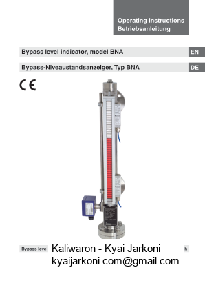
52. Design and function2.1 DescriptionThe bypass level indicators work according to the principle of permanent magnet. This changes its position depending on the level of the medium. Magnetic indicators, switches and level sensors are mounted to the outside of the bypass tube and actuated by the magnetic 2.2 Scope of delivery Cross-check scope of delivery with delivery note. 3. Safety 3.1 Explanation of symbols DANGER! indicates a directly dangerous situation resulting in serious injury or death, if not avoided. WARNING! indicates a potentially dangerous situation that can result in serious injury or death, if not avoided. CAUTION! indicates a potentially dangerous situation that can result in light injuries or damage to property or the environment, if not avoided. 2. Design and function / 3. Safety
PAGE – 6 ============
6Information points out useful tips, recommendations and information for 3.2 Intended useThe bypass level indicator serves for continuously measuring the level of liquids in vessels. and materials. The liquids must not have any large contamination or coarse particulates and must not have a tendency to crystallise. Ensure resistant to the medium being monitored. Not suitable for dispersions, abrasive liquids, highly viscous media and colours. This instrument is not permitted to be used in hazardous areas! For these areas, bypass level indicators with approval (e.g. in accordance with ATEX) are required. be observed. Do not operate the instrument in the direct vicinity of ferromagnetic environments (min. distance 50 mm). Do not operate the instrument in the immediate vicinity of strong The bypass level indicators must not be exposed to heavy mechanical strain (impact, bending, vibration). The instrument has been designed and built solely for the intended use described here, and may only be used accordingly. The manufacturer shall not be liable for claims of any type based on operation contrary to the intended use. 3. Safety
PAGE – 8 ============
83.5 WARNING! Improper handling can result in considerable injury and damage to equipment. The activities described in these operating instructions may only be carried out by skilled personnel who have the qualifications described below. Skilled personnelSkilled personnel, authorised by the operator, are understood to be personnel who, based on their technical training, knowledge of measurement and control technology and on their experience and directives, are capable of carrying out the work described and independently recognising potential hazards. 3.6 Personal protective equipment The personal protective equipment is designed to protect the skilled personnel from hazards that could impair their safety or health during work. When carrying out the various tasks on and with the instrument, the skilled personnel must wear personal protective equipment. Follow the instructions displayed in the work area regarding personal protective equipment! The requisite personal protective equipment must be provided by the operating company. 3. Safety
PAGE – 9 ============
3.7 Labelling, safety marks Product label (examples) Material of bypass chamber PS: Design pressure PT: Test pressure Permissible medium temperature range Density of the mediumMeasuring point numberSerial numberBefore mounting and commissioning the instrument, ensure you read the operating instructions! 3. Safety
PAGE – 10 ============
104. Transport, packaging and storage 4.1 Transport Check the bypass level indicator for any damage that may have been caused by transport. Obvious damage must be reported immediately. 4.2 Packaging and storage Do not remove packaging until just before commissioning. 5. Commissioning, operation Observe all instructions given on the shipment packaging for removing the transportation safety devices. Remove the bypass level indicator carefully from the packaging! When unpacking, check all components for any external damage. 5.1 Mounting preparation bypass chamber and remove the transport sleeve. Remove the protection caps of the process connections. Ensure that the sealing faces of the vessel or bypass level indicator are clean and do not show any mechanical damage. Check the connection dimensions (centre-to-centre distance) and the alignment of the process connections on the vessel. 4. Transport / 5. Commissioning, operation
PAGE – 11 ============
11Initialisation of magnetic display and magnetic switch display and then back down again. Align additionally mounted magnetic switches on the basis of the same principle. For bypass level indicators with insulation and magnetic displays must be moved up and down inside the tube. For magnetic displays with purge gas connections, these connections must have an airtight seal. Please refer in this case to the mounting and operating instructions for magnetic displays with purge gas connections as well. 5.2 Mounting Observe the torque values of Install the bypass level indicator without tension. In the selection of the mounting material (sealings, screws, washers and nuts), take the process conditions into account. The suitability of the sealing must medium and its vapours. T = upper projection M = centre-to-centre distance U = lower projection 5. Commissioning, operation
35 KB – 36 Pages