Technical information. Operating limits and tolerances of platinum resistance thermometers per DIN EN IEC 60751. WIKA data sheet IN 00.17. Page 1 of 8.
121 KB – 8 Pages
PAGE – 1 ============
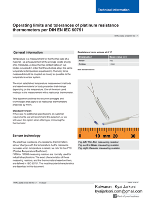
Operating limits and tolerances of platinum resistance thermometers per DIN EN IEC 60751 WIKA data sheet IN 00.17Page 1 of 8 Fig. centre: Glass measuring resistor Fig. right: Ceramic measuring resistor General information Temperature is a measurement for the thermal state of a material – so a measurement of the average kinetic energy of its molecules. A close thermal contact between two bodies is needed in order that these bodies adopt the same temperature (temperature equalisation). The body to be measured should be coupled as closely as possible to the temperature sensor system. The most established temperature measurement methods are based on material or body properties that change depending on the temperature. One of the most-used methods is the measurement with a resistance thermometer. This document outlines the recurrent concepts and technologies that apply to all resistance thermometers produced by WIKA. Standard version requirements, we will recommend this selection, or we thermometer. Sensor technologyThe electrical resistance of a resistance thermometer’s sensor changes with the temperature. As the resistance increases when temperature is raised, we refer to it as PTC (Positive Temperature CPt100 or Pt1000 measuring resistors are normally used for industrial applications. The exact characteristics of these measuring resistors, and the thermometers based on them, are described in this document. Resistance basic values at 0 °C Designation Pt100100Pt10001,000Bold: Standard version
PAGE – 2 ============
Measuring resistor designs Those measuring resistors used in thermometers can be wire-wound measuring resistors (W = Wire- Wound) or Film). applied to a ceramic carrier plate. Then, connecting wires are glass. 1) High vibration resistance Very small size the temperature range or an explicit customer request exclude them. In this design, a very thin platinum wire is encased within a round protective body. This design has been well-established for decades and is accepted worldwide. insulating material. Glass measuring resistor Ceramic measuring resistor Glass measuring resistor within a glass body. The glass measuring resistor is characterised by: 1) High vibration resistance Ceramic measuring resistor The platinum wire of a ceramic measuring resistor is spiral-wound and located in a cylindrical cavity in the protective body. The ceramic measuring resistor is characterised by: 1) Limited vibration resistance
PAGE – 3 ============
red whitered whitered red whitered whiteSensor connection methods 2-wire connection The lead resistance to the sensor is recorded as an error is not advisable when using Pt100 measuring resistors for tolerance classes A and AA, since the electrical resistance of the connecting cables and their own temperature dependency are fully included in the measuring result and thus falsify it. Applications Standard when using Pt1000 measuring resistors far as possible. The maximum length of the connecting cable depends on the conductor cross-section and the compensation options of the evaluation electronics (transmitter, display, controller or process control system). Applications Connecting cables up to approx. 30 m 4-wire connection result is completely eliminated since any possible asymmetries in the connecting cable’s lead resistance are also compensated.The maximum length of the connecting cable depends on the conductor cross-section and the compensation options of the evaluation electronics (transmitter, display, disconnecting the unnecessary conductors. Applications Laboratory technology Calibration technology Tolerance class A or AA Connecting cables up to 1,000 mDual sensors The combination of black and yellow is reserved for an (e.g. small diameter) dual sensors are not possible for technical reasons. Page 3 of 8
PAGE – 4 ============
Relationship between temperature and resistance This clear relationship can be described by mathematical formulae. irrespective of the resistor design: Rt = R0AtC (tŁ t³ ] Rt = R0At ]Legend: t= Rt=Resistance in ohms at the measured temperature R0= A=3.9083 Ł 10-3-1)=Ł 10-7)C=Ł 10)Operating limits and tolerance classes in the possible tolerances at the operating temperatures. ClassTemperature range in °C Tolerance value B B -196 – +600-196 – +600-50 – +500-50 – +500AA1)1)AAAA1)1) Bold: Standard version with built-in measuring resistors can be operated in a temperature range outside the temperature range of the The following must be observed regarding the compliance with the tolerance class: insert was operated above or below the class A temperature range. The dwell time is not relevant here.
PAGE – 5 ============
Max. permissible deviation in °C (irrespective of the sign) Temperature in °C Class AClass AAClass AClass AAMax. permissible deviation in °C (irrespective of the sign) Tolerance value IEC 60751 for resistance thermometers with wire-wound measuring resistors Temperature in °C
PAGE – 6 ============
Tolerance class B Tolerance class A Tolerance class AA 5080100-0.30-0.10110150130.13130.77200300 This table can be used to check the evaluation electronics, e.g. by means of a decade resistor: This means if the sensor or the measuring resistor is simulated by a decade resistor, the evaluation electronics must display a temperature value within the limit values temperatures. This means if a temperature standard is available, the resistance value of the test item must lie within the limits Temperature in °C Tolerance class B Tolerance class A Tolerance class AA -196—100–5080.0980.38-3088.30099.8820107.87100138.81138.37150250193.91300-450-500–600–
121 KB – 8 Pages