Cleaver-Brooks Model CB Boilers in sizes ranging from 125 through 200 boiler horsepower for the following fuels: Series 100 Light Oil (No. 2).
136 KB – 170 Pages
PAGE – 2 ============
SAFETY PRECAUTIONS AND ABBREVIATIONS Safety Precautions It is essential to read and understand the following safety precautions before attempting to operate the equipment. Failure to follow these precautions may result in damage to equipment, serious personal injury, or death. A complete understanding of this manual is required before attempting to start-up, operate or maintain the equipment. The equipment should be operated only by personnel who have a working knowledge and understanding of the equipment. The following symbols are used throughout this manual: !DANGER WARNING This symbol indicates a potentially hazardous situation which, if not avoided, could result in serious personal injury, or death. !DANGER CAUTION This symbol indicates a potentially hazard-ous situation which, if not avoided, could re- sult in damage to the equipment. Note: This symbol indicates information that is vital to the operation of this equipment. Abbreviations Following is an explanation of the abbreviations, acronyms, and symbols used in this manual. AC Alternating Current AR Automatic Reset ASME American Society of Mechanical Engineers ASTM American Society of Testing and Materials BHP Boiler Horsepower BTU British Thermal Unit ° C Degrees Celsius CFH Cubic Feet per Hour Cu Ft Cubic Feet DC Direct Current ° F Degrees Fahrenheit FM Factory Mutual FSFlame Safeguard ftFeet GPM Gallons per Minute Hd Head HT Height HTB High Turndown Burner HZ Hertz In H 2 OInches of Water IRI Industrial Risk Insurance Lb Pound LWCO Low-Water Cut-Off MMillion MFD Micro-Farad MR Manual Reset NECNational Electric Code No. Number pH Measure of the degree of acid or base of a solutionP/N Part Number PPM Parts Per Million PR Program Relay psi Pounds Per Square Inch SAE Society of Automotive Engineers scfh Standard Cubic Feet per Hour T Temperature TC Temperature Control TI Temperature Gauge
PAGE – 3 ============
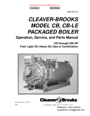
MODEL CB, CB-LE PACKAGED BOILER Operation, Service, and Parts Manual 125 through 200 HP Fuel: Light Oil, Heavy Oil Gas or Combination Please direct purchase orders for replacement manuals to your local Cleaver-Brooks authorized representative Manual Part No. 750-184 8/98Printed in U.S.A. Ó Cleaver-Brooks 1998 NOTE: If you have a CB-HAWK Ô Boiler Management ControlSystem, refer to CB-HAWK Installation, Operating and ServiceManual No. 750-133 during initial start up, and when referenc- ing Chapters 5, 6, and 7 in this manual.
PAGE – 4 ============
i TO: Owners, Operators and/or Maintenance Personnel This operating manual presents information that will help to properly operate and care for the equipment. Study its contents carefully. The unit will provide good service and continued operation if proper operating and maintenance instructions are fol- lowed. No attempt should be made to operate the unit until the principles of operation and all of the components are thoroughly understood. Failure to follow all applicable instructions and warnings may result in severe personal injury or death. It is the responsibility of the owner to train and advise not only his or her personnel, but the contractors’ personnel who are ser- vicing, repairing or operating the equipment, in all safety aspects.Cleaver-Brooks equipment is designed and engineered to give long life and excellent service on the job. The electrical and me- chanical devices supplied as part of the unit were chosen because of their known ability to perform; however, proper operating techniques and maintenance procedures must be followed at all times. Although these components afford a high degree of pro- tection and safety, operation of equipment is not to be considered free from all dangers and hazards inherent in handling and Þring of fuel.Any “automatic” features included in the design do not relieve the attendant of any responsibility. Such features merely free him of certain repetitive chores and give him more time to devote to the proper upkeep of equipment. It is solely the operatorÕs responsibility to properly operate and maintain the equipment. No amount of written instructions can replace intelligent thinking and reasoning and this manual is not intended to relieve the operating personnel of the responsibility for proper operation. On the other hand, a thorough understanding of this manual is required before attempting to operate, main- tain, service, or repair this equipment.Because of state, local, or other applicable codes, there are a variety of electric controls and safety devices which vary consid- erably from one boiler to another. This manual contains information designed to show how a basic burner operates. Operating controls will normally function for long periods of time and we have found that some operators become lax in their daily or monthly testing, assuming that normal operation will continue indeÞnitely. Malfunctions of controls lead to uneconom- ical operation and damage and, in most cases, these conditions can be traced directly to carelessness and deÞciencies in testing and maintenance.It is recommended that a boiler room log or record be maintained. Recording of daily, weekly, monthly and yearly maintenance activities and recording of any unusual operation will serve as a valuable guide to any necessary investigation. Most instances of major boiler damage are the result of operation with low water. We cannot emphasize too strongly the need for the operator to periodically check his low water controls and to follow good maintenance and testing practices. Cross-con- necting piping to low water devices must be internally inspected periodically to guard against any stoppages which could ob- struct the free ßow of water to the low water devices. Float bowls of these controls must be inspected frequently to check for the presence of foreign substances that would impede ßoat ball movement. The waterside condition of the pressure vessel is of extreme importance. Waterside surfaces should be inspected frequently to check for the presence of any mud, sludge, scale or corrosion. The services of a qualiÞed water treating company or a water consultant to recommend the proper boiler water treating practices are essential. The operation of this equipment by the owner and his or her operating personnel must comply with all requirements or regula- tions of his insurance company and/or other authority having jurisdiction. In the event of any conßict or inconsistency between such requirements and the warnings or instructions contained herein, please contact Cleaver-Brooks before proceeding. DO NOT OPERATE, SERVICE, OR REPAIR THIS EQUIPMENT UNLESS YOU FULLY UNDERSTAND ALL APPLICABLE SECTIONS OF THIS MANUAL. DO NOT ALLOW OTHERS TO OPERATE, SERVICE, OR REPAIR THIS EQUIPMENT UNLESS THEY FULLY UNDERSTAND ALL APPLICABLE SECTIONS OF THIS MANUAL. FAILURE TO FOLLOW ALL APPLICABLE WARNINGS AND INSTRUCTIONS MAY RESULT IN SEVERE PERSONAL INJURY OR DEATH. ! DANGER WARNING
PAGE – 5 ============
TABLE OF CONTENTS Chapter 1 Basics of Firetube Operation A. General. . . . . . . . . . . . . . . . . . . . . . . . . . . . . . . . . . . . . . . . . . . . . . . . . . . . . . . . . . . . . . . . . . . . . . . . 1-1 B. The Boiler. . . . . . . . . . . . . . . . . . . . . . . . . . . . . . . . . . . . . . . . . . . . . . . . . . . . . . . . . . . . . . . . . . . . . . 1-2 C. Construction. . . . . . . . . . . . . . . . . . . . . . . . . . . . . . . . . . . . . . . . . . . . . . . . . . . . . . . . . . . . . . . . . . . . 1-3 D. Steam Controls (All Fuels) . . . . . . . . . . . . . . . . . . . . . . . . . . . . . . . . . . . . . . . . . . . . . . . . . . . . . . . . 1-5 E. Hot Water Controls (All Fuels). . . . . . . . . . . . . . . . . . . . . . . . . . . . . . . . . . . . . . . . . . . . . . . . . . . . . . 1-7 F. Induced Flue Gas Recirculation Components (CB-LE). . . . . . . . . . . . . . . . . . . . . . . . . . . . . . . . . . . 1-9 Chapter 2 Burner Operation and Control A. The Burner. . . . . . . . . . . . . . . . . . . . . . . . . . . . . . . . . . . . . . . . . . . . . . . . . . . . . . . . . . . . . . . . . . . . . 2-1 B. Control And Component Function. . . . . . . . . . . . . . . . . . . . . . . . . . . . . . . . . . . . . . . . . . . . . . . . . . . 2-4 C. Components Common To All Boilers . . . . . . . . . . . . . . . . . . . . . . . . . . . . . . . . . . . . . . . . . . . . . . . . 2-4 D. Controls For Gas Firing. . . . . . . . . . . . . . . . . . . . . . . . . . . . . . . . . . . . . . . . . . . . . . . . . . . . . . . . . . . 2-5 E. Controls Common To Oil-Fired Boiler (Including Combination). . . . . . . . . . . . . . . . . . . . . . . . . . . . . . . . . . . . . . . . . . . . . . . . . . . . . . . . . . . 2-8 F. Additional Controls For Heavy Oil. . . . . . . . . . . . . . . . . . . . . . . . . . . . . . . . . . . . . . . . . . . . . . . . . . 2-11 G. Controls For Combination Burners Only. . . . . . . . . . . . . . . . . . . . . . . . . . . . . . . . . . . . . . . . . . . . . 2-12 H. Combustion Air . . . . . . . . . . . . . . . . . . . . . . . . . . . . . . . . . . . . . . . . . . . . . . . . . . . . . . . . . . . . . . . . 2-12 I. Automatic Ignition. . . . . . . . . . . . . . . . . . . . . . . . . . . . . . . . . . . . . . . . . . . . . . . . . . . . . . . . . . . . . . . 2-13 J. Atomizing Air . . . . . . . . . . . . . . . . . . . . . . . . . . . . . . . . . . . . . . . . . . . . . . . . . . . . . . . . . . . . . . . . . . 2-13 K. Oil Fuel Flow – Light Oil. . . . . . . . . . . . . . . . . . . . . . . . . . . . . . . . . . . . . . . . . . . . . . . . . . . . . . . . . 2-13 L. Oil Fuel Flow – Heavy Oil . . . . . . . . . . . . . . . . . . . . . . . . . . . . . . . . . . . . . . . . . . . . . . . . . . . . . . . . 2-16 M. Gas Fuel Flow. . . . . . . . . . . . . . . . . . . . . . . . . . . . . . . . . . . . . . . . . . . . . . . . . . . . . . . . . . . . . . . . . 2-16 N. Modulating Firing . . . . . . . . . . . . . . . . . . . . . . . . . . . . . . . . . . . . . . . . . . . . . . . . . . . . . . . . . . . . . . 2-16 Chapter 3 Waterside Care And Requirements A. General. . . . . . . . . . . . . . . . . . . . . . . . . . . . . . . . . . . . . . . . . . . . . . . . . . . . . . . . . . . . . . . . . . . . . . . . 3-1 B. Water Requirements. . . . . . . . . . . . . . . . . . . . . . . . . . . . . . . . . . . . . . . . . . . . . . . . . . . . . . . . . . . . . . 3-1 C. Water Treatment. . . . . . . . . . . . . . . . . . . . . . . . . . . . . . . . . . . . . . . . . . . . . . . . . . . . . . . . . . . . . . . . . 3-5 D. Cleaning. . . . . . . . . . . . . . . . . . . . . . . . . . . . . . . . . . . . . . . . . . . . . . . . . . . . . . . . . . . . . . . . . . . . . . . 3-5 E. Boil-out Of A New Unit. . . . . . . . . . . . . . . . . . . . . . . . . . . . . . . . . . . . . . . . . . . . . . . . . . . . . . . . . . . 3-6 F. Washing Out . . . . . . . . . . . . . . . . . . . . . . . . . . . . . . . . . . . . . . . . . . . . . . . . . . . . . . . . . . . . . . . . . . . . 3-7 G. Blowdown Steam Boiler . . . . . . . . . . . . . . . . . . . . . . . . . . . . . . . . . . . . . . . . . . . . . . . . . . . . . . . . . . 3-7 H. Periodic Inspection. . . . . . . . . . . . . . . . . . . . . . . . . . . . . . . . . . . . . . . . . . . . . . . . . . . . . . . . . . . . . . . 3-9 I. Preparation For Extended Lay-up . . . . . . . . . . . . . . . . . . . . . . . . . . . . . . . . . . . . . . . . . . . . . . . . . . . . 3-9 ii
PAGE – 6 ============
TABLE OF CONTENTS(continued) Chapter 4 Sequence Of Operation A. General. . . . . . . . . . . . . . . . . . . . . . . . . . . . . . . . . . . . . . . . . . . . . . . . . . . . . . . . . . . . . . . . . . . . . . . . 4-1 B. Circuit And Interlock Controls. . . . . . . . . . . . . . . . . . . . . . . . . . . . . . . . . . . . . . . . . . . . . . . . . . . . . . 4-1 C. Sequence Of Operation – Oil Or Gas. . . . . . . . . . . . . . . . . . . . . . . . . . . . . . . . . . . . . . . . . . . . . . . . . 4-2 D. Flame Loss Sequence. . . . . . . . . . . . . . . . . . . . . . . . . . . . . . . . . . . . . . . . . . . . . . . . . . . . . . . . . . . . . 4-3 Chapter 5 Starting And Operating Instructions A. General Preparation for Start-up – All Fuels . . . . . . . . . . . . . . . . . . . . . . . . . . . . . . . . . . . . . . . . . . . 5-1 B. Control Settings-Steam and Hot Water . . . . . . . . . . . . . . . . . . . . . . . . . . . . . . . . . . . . . . . . . . . . . . . 5-2 C. Gas Pilot . . . . . . . . . . . . . . . . . . . . . . . . . . . . . . . . . . . . . . . . . . . . . . . . . . . . . . . . . . . . . . . . . . . . . . 5-3 D. Atomizing Air. . . . . . . . . . . . . . . . . . . . . . . . . . . . . . . . . . . . . . . . . . . . . . . . . . . . . . . . . . . . . . . . . . . 5-3 E. Firing Preparations for No. 2 Oil (Series 100-200) . . . . . . . . . . . . . . . . . . . . . . . . . . . . . . . . . . . . . . 5-4 F. Firing Preparations for No. 6 Oil (Series 400-600) . . . . . . . . . . . . . . . . . . . . . . . . . . . . . . . . . . . . . . 5-6 G. Firing Preparations for Gas (Series 200-400-700). . . . . . . . . . . . . . . . . . . . . . . . . . . . . . . . . . . . . . . 5-7H. Induced Flue Gas Recirculation Set Up. . . . . . . . . . . . . . . . . . . . . . . . . . . . . . . . . . . . . . . . . . . . . . . 5-8 I. Start-up, Operating and Shutdown – All Fuels . . . . . . . . . . . . . . . . . . . . . . . . . . . . . . . . . . . . . . . . . 5-10 J. Control Operational Tests and Checks . . . . . . . . . . . . . . . . . . . . . . . . . . . . . . . . . . . . . . . . . . . . . . . 5-11 Chapter 6 Adjustment Procedures A. General. . . . . . . . . . . . . . . . . . . . . . . . . . . . . . . . . . . . . . . . . . . . . . . . . . . . . . . . . . . . . . . . . . . . . . . . 6-1 B. Linkage – Modulating Motor & Air Damper . . . . . . . . . . . . . . . . . . . . . . . . . . . . . . . . . . . . . . . . . . . 6-2C. Modulating Motor . . . . . . . . . . . . . . . . . . . . . . . . . . . . . . . . . . . . . . . . . . . . . . . . . . . . . . . . . . . . . . . 6-3 D. Modulating Motor Switches Low Fire and High Fire . . . . . . . . . . . . . . . . . . . . . . . . . . . . . . . . . . . . 6-3 E. Burner Operating Controls General . . . . . . . . . . . . . . . . . . . . . . . . . . . . . . . . . . . . . . . . . . . . . . . . . . 6-4 F. Modulating Pressure Controls (Steam). . . . . . . . . . . . . . . . . . . . . . . . . . . . . . . . . . . . . . . . . . . . . . . . 6-6 G. Operating Limit Pressure Control (Steam) . . . . . . . . . . . . . . . . . . . . . . . . . . . . . . . . . . . . . . . . . . . . 6-6 H. High Limit Pressure Control – (Steam) . . . . . . . . . . . . . . . . . . . . . . . . . . . . . . . . . . . . . . . . . . . . . . . 6-6 I. Modulating Temperature Control – (Hot Water) . . . . . . . . . . . . . . . . . . . . . . . . . . . . . . . . . . . . . . . . . 6-6 J. Operating Limit Temperature Control – (Hot Water) . . . . . . . . . . . . . . . . . . . . . . . . . . . . . . . . . . . . . 6-7 K. High Limit Temperature Control – (Hot Water). . . . . . . . . . . . . . . . . . . . . . . . . . . . . . . . . . . . . . . . . 6-7L. Low-Water Cutoff Devices. . . . . . . . . . . . . . . . . . . . . . . . . . . . . . . . . . . . . . . . . . . . . . . . . . . . . . . . . 6-7 M. Combustion Air Proving Switch . . . . . . . . . . . . . . . . . . . . . . . . . . . . . . . . . . . . . . . . . . . . . . . . . . . . 6-7 N. Atomizing Air Proving Switch. . . . . . . . . . . . . . . . . . . . . . . . . . . . . . . . . . . . . . . . . . . . . . . . . . . . . . 6-7 O. Gas Pilot Flame Adjustment . . . . . . . . . . . . . . . . . . . . . . . . . . . . . . . . . . . . . . . . . . . . . . . . . . . . . . . 6-8 P. Gas Pressure and Flow Information . . . . . . . . . . . . . . . . . . . . . . . . . . . . . . . . . . . . . . . . . . . . . . . . . . 6-9 Q. Gas Fuel Combustion Adjustment. . . . . . . . . . . . . . . . . . . . . . . . . . . . . . . . . . . . . . . . . . . . . . . . . . 6-11 R. Low-Gas Pressure Switch . . . . . . . . . . . . . . . . . . . . . . . . . . . . . . . . . . . . . . . . . . . . . . . . . . . . . . . . 6-13 S. High-Gas Pressure Switch . . . . . . . . . . . . . . . . . . . . . . . . . . . . . . . . . . . . . . . . . . . . . . . . . . . . . . . . 6-14 T. Fuel Oil Pressure and Temperature – General. . . . . . . . . . . . . . . . . . . . . . . . . . . . . . . . . . . . . . . . . . 6-14 U. Fuel Oil Combustion Adjustment . . . . . . . . . . . . . . . . . . . . . . . . . . . . . . . . . . . . . . . . . . . . . . . . . . 6-17 iii
PAGE – 8 ============
Chapter 9 Customer Service And Parts Front Door, Inner Door. . . . . . . . . . . . . . . . . . . . . . . . . . . . . . . . . . . . . . . . . . . . . . . . . . . . . . . . . . . . . . 3-5 Rear Head . . . . . . . . . . . . . . . . . . . . . . . . . . . . . . . . . . . . . . . . . . . . . . . . . . . . . . . . . . . . . . . . . . . . . . . . . . 6 Dry Oven & Liner Tile . . . . . . . . . . . . . . . . . . . . . . . . . . . . . . . . . . . . . . . . . . . . . . . . . . . . . . . . . . . . . . 7, 8 Impellers. . . . . . . . . . . . . . . . . . . . . . . . . . . . . . . . . . . . . . . . . . . . . . . . . . . . . . . . . . . . . . . . . . . . . . . . .9,10 Jackshafts, Mod Motor, Air Damper Linkage. . . . . . . . . . . . . . . . . . . . . . . . . . . . . . . . . . . . . . . . . . . 11-15 Burner Drawer . . . . . . . . . . . . . . . . . . . . . . . . . . . . . . . . . . . . . . . . . . . . . . . . . . . . . . . . . . . . . . . . . . 16, 17 Burner Housing. . . . . . . . . . . . . . . . . . . . . . . . . . . . . . . . . . . . . . . . . . . . . . . . . . . . . . . . . . . . . . . . . . 18, 19 Flame Control. . . . . . . . . . . . . . . . . . . . . . . . . . . . . . . . . . . . . . . . . . . . . . . . . . . . . . . . . . . . . . . . . . . 20, 21 Entrance Box & Fuses . . . . . . . . . . . . . . . . . . . . . . . . . . . . . . . . . . . . . . . . . . . . . . . . . . . . . . . . . . . . 22, 23 Front Head Electrical . . . . . . . . . . . . . . . . . . . . . . . . . . . . . . . . . . . . . . . . . . . . . . . . . . . . . . . . . . . . . 24, 25 Electric Oil Heater . . . . . . . . . . . . . . . . . . . . . . . . . . . . . . . . . . . . . . . . . . . . . . . . . . . . . . . . . . . . . . . 26, 27 Oil Emission Steam Electric Heater. . . . . . . . . . . . . . . . . . . . . . . . . . . . . . . . . . . . . . . . . . . . . . . . . . 28-30 Air Compressor /Air Line Piping . . . . . . . . . . . . . . . . . . . . . . . . . . . . . . . . . . . . . . . . . . . . . . . . . . . . 31-34 Light Oil / Air Piping Front Head. . . . . . . . . . . . . . . . . . . . . . . . . . . . . . . . . . . . . . . . . . . . . . . . . . . . 35, 36 Gas Trains. . . . . . . . . . . . . . . . . . . . . . . . . . . . . . . . . . . . . . . . . . . . . . . . . . . . . . . . . . . . . . . . . . . . . . 37, 38 Pressure Controls . . . . . . . . . . . . . . . . . . . . . . . . . . . . . . . . . . . . . . . . . . . . . . . . . . . . . . . . . . . . . . . . . . . 39 Temperature Controls . . . . . . . . . . . . . . . . . . . . . . . . . . . . . . . . . . . . . . . . . . . . . . . . . . . . . . . . . . . . . 40, 41 Water Column. . . . . . . . . . . . . . . . . . . . . . . . . . . . . . . . . . . . . . . . . . . . . . . . . . . . . . . . . . . . . . . . . . . 42, 43 v Notes
PAGE – 9 ============
750-1841-1 CHAPTER 1Basics of Firetube Operation A. GENERAL Firetube boilers are available for low or high pressure steam, or for hot water applications. Firetube boilers are typically used for applications ranging from 15 to 800 horsepower. A Þretube boiler is a cylindrical vessel, with horizontal tubes passing through and connected to the front and rear tube sheets. The vessel contains the water and absorbs the energy generated from the ßame. The front door and rear door provide the seal to contain the hot combustion gasses. Bafßes designed into the doors serve to redirect the combustion gasses through the various Þretube passages. The ßame originates in the furnace. As the combustion gasses travel down the furnace and through the various Þretube channels, heat from the ßame and combustion gasses is transferred to the water. Transferred energy develops into the required steam or hot water. The primary purpose of the boiler is to supply energy to the facilityÕs operations – for heat, manufacturing process, laundry, kitchen, etc. The nature of the facilityÕs operation will dictate whether a steam or hot water boiler should be used. Note: If your boiler is equipped with a CB- HAWK Ô boiler management control system, refer to CB-HAWK Installation, Operating and Servicing Manual No. 750- 133 for information regarding controls discussed in Chapter 1. Figure: 1-1 Firetube Cut Away(Typical) A. General. . . . . . . . . . . . . . . . . . . . . . . . . . . . . . . . . . 1-1 B. The Boiler. . . . . . . . . . . . . . . . . . . . . . . . . . . . . . . . 1-2 C. Construction . . . . . . . . . . . . . . . . . . . . . . . . . . . . . . 1-3 D. Steam Controls (All Fuels). . . . . . . . . . . . . . . . . . . 1-5 E. Hot Water Controls (All Fuels). . . . . . . . . . . . . . . . 1-7 F. Induced Flue Gas Recirculation Components. . . . . 1-9
PAGE – 10 ============
Chapter 1Basics of Firetube Operation 1-2750-184 The general information in this manual applies directly toCleaver-Brooks Model CB Boilers in sizes ranging from 125 through 200 boiler horsepower for the following fuels: Series 100 Light Oil (No. 2) Series 200 Light Oil (No. 2) Or Gas Series 400 Heavy Oil (No. 6) Or Gas Series 600 Heavy Oil (No. 6) Only Series 700 Gas Only Note: Although the Series 400 or 600 burner is designed and designated to burn No. 6 oil, the burner will handle grades 4 and 5 equally well, with some possible adjustments. While the manual contains pertinent information on No. 6 fuel oil, all references to No. 6 fuel should be considered applicable to all grades of heavy oil. The LE Option, available on Cleaver-Brooks Firetube Boilers, reduces Nitrogen Oxide (NOx) emissions, a major precursor to ozone pollution (smog). Carbon Monoxide (CO) emissions also tend to be lower, due to increased turbulence caused by the addition of the ßue gases into the combustion air stream, thereby improving combustion. Note: For information on IFGR when Þring heavy oil, review the Operation and Maintenance manual for Heavy Oil Isolation 750-171 The LE Option is used on Cleaver-Brooks Model CB Firetube boilers Þring either natural gas and/or light oil, and is compatible with both hot water and steam systems. The IFGR system mixes a portion of the relatively cool ßue gas from the exit of the fourth-pass tubes with the incoming combustion air to reduce the furnace ßame temperature, thereby reducing NOx emissions. In this approach, the combustion air fan handles both the combustion air and the recirculated ßue gases. Accordingly, this method is called Induced Flue Gas Recirculation (IFGR), because the ßue gas is ÒinducedÓ into the fan inlet. The LE Option, with its various levels of IFGR systems, can affect the selection of the combustion air fan, motor, burner, and other components. Several different system conÞgurations are available, depending on the requirements for NOx emissions and the fuels used. All systems use similar primary components, but may have different linkage controls, IFGR damper, fan, and motor sizes. Always order genuine Cleaver-Brooks parts from your local Cleaver-Brooks authorized representative. The boiler and related equipment installation are to be incompliance with the standards of the National Board of Fire Underwriters. Installation should also conform to state and local codes governing such equipment. Prior to installation, the proper authorities having jurisdiction are to be consulted, permits obtained, etc. All boilers in the above series comply, when equipped with optional equipment, to Industrial Risk Insurers (IRI), Factory Mutual (FM), or other insuring underwriters requirements. B. THE BOILER The Model CB boiler is a packaged Þretube boiler of welded steel construction and consists of a pressure vessel, burner, burner controls, forced draft fan, damper, air pump, refractory, and appropriate boiler trim. The horsepower rating of the boiler is indicated by the numbers following the fuel series. Thus, CB700-200 indicates a gas-Þred 200 hp boiler. The Þretube construction provides some characteristics that differentiate it from other boiler types. Because of its vessel size, the Þretube contains a large amount of water, allowing it to respond to load changes with minimum variation in steam pressure. Firetube boilers are rated in boiler horsepower (BHP), which should not be confused with other horsepower measure- ments. Hot water is commonly used in heating applications with the boiler supplying water to the system at 180 ° F to 220 ° F. The operating pressure for hot water heating systems usually is 30 psig to 125 psig. Rated Capacity125 through 200hp Operating Pressure Steam 15-250 psig, or higher if speciÞedHot Water 30-250 psig or higher if speciÞedFuelOil or Gas or Combination Ignition Automatic FiringFull Modulation Through Operating RangesBurner (Oil)(Low Pressure) Air Atomizing Burner (Gas)Non-premix Ð OriÞced Type Air DamperRotary Type (Electrically Modulated)Steam TrimASME Code Water TrimASME Code
PAGE – 11 ============
Basics of Firetube OperationChapter 1 750-1841-3 Steam boilers are designed for low pressure or high pressure applications. Low pressure boilers are limited to 15 psig design, and are typically used for heating applications. High pressure boilers are typically used for process loads and can have a design pressure of 75 to 350 psig. Steam and hot water boilers are deÞned according to design pressure and operating pressure. Design pressure is the max- imum pressure used in the design of the boiler for the pur- pose of calculating the minimum permissible thickness or physical characteristics of the pressure vessel parts of the boiler. Typically, the safety valves are set at or below design pressure. Operating pressure is the pressure of the boiler at which it normally operates. The operating pressure usually is maintained at a suitable level below the setting of the pres- sure relieving valve(s) to prevent their frequent opening dur- ing normal operation. The type of service that your boiler is required to provide has an important bearing on the amount of waterside care it will require.!DANGER CAUTION Waterside care is of prime importance. For speciÞc information or assistance with your water treatment requirements, contact your Cleaver-Brooks service and parts represen- tative. Failure to follow these instructions could result in equipment damage Feedwater equipment should be checked and ready for use. Be sure that all valves, piping, boiler feed pumps, and receivers are installed in accordance with prevailing codes and practices. Water requirements for both steam and hot water boilers are essential to boiler life and length of service. Constant attention to water requirements will pay dividends in the form of longer life, less down-time, and prevention of costly repairs. Care taken in placing the pressure vessel into initial service is vital. The waterside of new boilers and new or remodeled steam or hot water systems may contain oil, grease or other foreign matter. A method of boiling out the vessel to remove accumulations is described in Chapter 3. The operator should be familiar with Chapter 3 before attempting to place the unit into operation. C. CONSTRUCTION Steam boilers designed for 15 psig and hot water boilers designed for 250 ° F at 125 psi or less are constructed inaccordance with Section IV, Power Boilers, of ASME Code. Steam boilers designed for operating pressures exceeding 15 psig are constructed in accordance with Section 1, Power Boilers, of the ASME Code. Hot water boilers designed for operating temperatures above 250 ° F or 125 psi are likewise built to ASME Code.
136 KB – 170 Pages