A The Aquablast machine requires a compressed air supply to operate. The compressed air requirement depends on the blast gun nozzle size and the pressure
143 KB – 24 Pages
PAGE – 1 ============
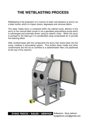
THE WETBLASTING PROCESS Wetblasting is the propulsion of a mixture of water and abrasive (a slurry) via a blast nozzle, which on impact cleans, degreases a nd removes debris. The water media slurry is contained within the cabi net sump, delivery of the slurry to the manual blast nozzle is via a glandles s polyurethane pump which is submerged and externally driven using an electri c motor. When the slurry is pumped to the blast gun it is accelerated using compressed air to provide the cleaning effect. After contact/impact with the components the slurry then drains back into the sump, creating a recirculating system. Fine broken down media and other contaminants are fed via an overflow to a sedimenta tion filter unit positioned at the rear of the machine.
PAGE – 3 ============
SECTION 1 INSTALLATION The Aquablast machine range does not normally requi re bolting to the floor except in special build units which may be unstable . INSTALLATION AND ANY NECESSARY GUARDING ARE NOT THE RESPONSIBILITY O F THE MANUFACTURER. The commissioning of the machine onc e installed should be carried out by a Vixen sales or service engineer or in conjunction with advice from our factory. 1.1 GENERAL INSTRUCTIONS A The machine should be sited on a firm, level base capable of supporting the weight of the machine and the compon ent loads not forgetting the water and abrasive weight also. In most cases the machine would be free standing. B The sedimentation box is normally situated at the back of the machine as near to the overflow as possible therefore preve nting long lengths of tubing which may block. C Water connection Πthe Aquablast requires a mains water connection to the rear of the machine. The mains water normally feeds the window wash and the hand operated rinse gun, which is also used to re-fill the machine with water. D Vapour Vent ΠThe machine has a 100mm circular ve nt fitted at the back on the top of the machine, this allows the mac hine not to have a positive pressure inside the blast machine. The 10 0mm vent can have a plastic extension pipe and adapter fitted which i s supplied separately, this prevents vapour debris falling onto the top of the machine. It is also possible (but rarely required) to connect the vent to an external wall via the extension pipe if required in ficlean roomfl situ ations for example.
PAGE – 4 ============
1.2 ELECTRICAL A A standard Aquablast cabinet should be connected to a 25amp 3 phase neutral & earth supply (including 3kw heater). Alt ernatively the machine can be supplied single phase, in this case the mach ine using the inverter can operate from a 16amp 240V single phase supply (excluding 3kw heater). B The pump motor is connected to the mains control panel by a small socket connection externally mounted on the plastic case. This can be unplugged allowing the pump and motor assembly to b e carried to a bench for service without disconnecting any wiring. C All electrical supplies and connections are the r esponsibility of the user. If on site any wiring connections are not suitable to the environment then this modification is not the manufacturers res ponsibility. WARNING: WITH 3 PHASE UNITS IT IS VITAL THAT THE DIRECTION OF THE MOTOR IS CHECKED BEFORE FILLING TH E MACHINE WITH WATER. RUNNING THE MACHINE IN THE WRONG DIRECTION WITH WAT ER WILL UNSCREW THE IMPELLER IN THE PUMP AND WILL REQU IRE DISMANTELING.
PAGE – 5 ============
1.3 COMPRESSED AIR A The Aquablast machine requires a compressed air s upply to operate. The compressed air requirement depends on the blast gun nozzle size and the pressure required to clean effectively. It is not normal to clean using air pressures great er than 60psi (4.5 bar) as the greater the air pressure the more vapour gen erated and visibility is impaired. Therefore to increase cleaning effici ency from the standard nozzle usually fitted (12.5mm) then a larger 14mm n ozzle can be fitted with a larger air jet using a greater volume of air . Typical air volumes are detailed in section 3.1
PAGE – 6 ============
SECTION 2 2.1 PRINCIPAL OF THE AQUABLAST OFF At the off position the machine is at rest with onl y the water heater and cabinet lighting switched on. When the machine is stood for thirty seconds or so, the media separates from the slurry and will se ttle at the base of the machine hopper. The liquid will be above which has the benefit of easy replacement when over contaminated. The liquid onl y may be drained through the upper ball valve (No. 11 on G.A. drawin g) and afterwards re-filled using the mains water hand gun, in the cases of a c losed loop system then the machine will require filling from an external h osepipe. Finally after re- filling a rust inhibitor/detergent maybe added if r equired.
PAGE – 8 ============
2.3 PRINCIPLE OF THE AQUABLAST RUNNING After initial running the water and abrasive are no w fully mixed to a slurry and the window wash will be adding mains wat er to the sump, all be it at only a few litres /hour. This additional water will exit the machine via the overflow. Typically small broken down media floati ng near the top of the water level will be finer than near the pump inlet. This water overflowing then will contain mostly debris and unwanted abrasive an d can be disposed of through the sedimentation box. The free standing s edimentation box can be emptied periodically firstly by draining the water off and disposing of, and then emptying the box of debris and broken down blast me dia.
PAGE – 9 ============
SEDIMENTATION FILTER AND CLOSED LOOP RINSE The purpose of the sedimentation filter is to separ ate solid particles from the water coming out of the overflow. It is inevitable that with the window washer and the mains water rinse gun using mains water tha t over hours of blasting the water level would increase if no overflow was f itted. The overflow serves another purpose though in bringing debris and soils out of the slurry which would otherwise over contaminate the blasting water slurry solution. There are two types of overflow systems. A Standard Open Drain Overflow This system simply has the sedimentation box situat ed at the rear of the machine and accepts water via the overflow into the sedimentation box. The baffle within this box retains particles of abr asive (usually broken down) together with debris and soils which is remov ed when blasting. The debris settles to the base of the sedimentation filter and is mostly trapped in the corner of the baffle as shown. Peri odically the filter will need emptying and water may usually be disposed dow n a foul drain and the solid particles in a waste bin. The freque ncy on emptying the sedimentation box will vary depending on the usage of the mains water rinse gun and the water flow directed to the window washer. As both of these use mains water and are operator dependent so is the frequency of water and solid disposal.
PAGE – 10 ============
B Close Loop Rinse This system consists of the sedimentation box as st andard but have several options. An electrically operated solenoid valve which only allows water to drain via the overflow after the blasting operation cease s. The time delay is adjustable but usually 1 Π2 minutes depending on c ourse or finer abrasives used. The purpose of the delay is to all ow the abrasives to settle (with finer abrasives the delay should be lo nger than with coarser abrasives) in the machine hopper and following this the valve opens and allows over filling of water to exit via the ov erflow tube to the sedimentation filter. It would be expected therefore that this system wou ld differentiate better with fine broken down abrasive (which should be discarded anyway) and good re-usable abrasive. Therefore wat er exiting the overflow will be of higher quality or less contamin ated. The closed loop system has a paper filter and carrier supplied and due to the water being less contaminated the debris exiting is colle cted mainly on the paper roll. The paper roll needs to be pulled throu gh manually when it becomes over contaminated. A 12volt pump is fitted to the base of the sedimentation filter which supplies relatively clea n water to the rinse gun. Therefore the only overfilling occurring with use is the window wiper which is usually consuming 5 litres of mains water/hour and therefore allowing hours of blasting before the sed imentation filter needs emptying. The closed loop system can be retrofitted to a mach ine and costs details etc are available through your distributor or the manufacturer.
PAGE – 11 ============
SECTION 3 THE BLAST GUN The blast gun fitted to the Aquablast is a polyuret hane moulded unit designed to resist wear due to abrasive and water running th rough it. The blast gun consists of 4 components as shown in the exploded d iagram below. 1 Air jet (hardened steel) 2 Grub screw 3 Polyurethane gun body 4 Nozzle 5 Nozzle retaining ring All the above parts will wear in time and require r eplacement, however the first component to wear is the hardened steel air j et. This is located or held in the correct position using the grub screw shown. R otation of the air jet periodically will extend the life of this, examinat ion is quite easy when the nozzle is removed. The same principle of rotation will also increase the life of the nozzle. IMPORTANT ΠPLEASE OBSERVE THE POSITION OF THE AIRJ ET WITHIN THE GUN BODY, WHERE THE TIP OF THE AIRJET IS FLUSH WITH THE NOZZLE INLET. See diagram below.
143 KB – 24 Pages