These types of tumble belt shot blasting machines are very easy to operate. Page 3. Blast cabinet. – External structure with robust and compact design made
481 KB – 7 Pages
PAGE – 2 ============
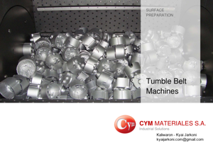
The process starts with the loading of the parts on the belt either manually or through an automatic loading system. Once the door is closed the blasting cycle initiate s. The wheels and the belt start spinning producing a continuous rotation of the parts thereby ensuring that all components are exposed to the sho t blasting stream for consistent cleaning. When the blasting process finishes, the machine sto ps automatically allowing the unloading of the parts to take place. Then, the operator moves the belt in the reverse direction to prepare the ma chine for a new load. . Tumble belt shot blasting machines are the most uni versal among all shotblasters as their design makes them suitable fo r processing parts of different sizes in bulk loads. Cym Materiales SA manufactures two groups of tumble belt machines. The blasting units belonging to the first group are rather small with one turbine and a shot capacity range of 20 to 60 liter s while the second group has two turbines and a shot capacity from 130 to 900 liters. These types of tumble belt shot blasting machines a re very easy to operate.
PAGE – 3 ============
Blast cabinet – External structure with robust and compact design made of SAE1010 steel – Cast steel Liner plates ( 64Rc) and manganese steel plates to protect cabinet – Loading / unloading door for parts with manual or pneumatic opening according to model – Screw conveyor – Spiral 15b30 boron-steel – Wide easily accessible rear door for internal maintenance of the cabinet and bottom of the bucket elevator Belt conveyor Two options of high resistance to wear belt – G Model: Rubber – T Model Steel Loading & Unloading – Hydraulic parts loader – Vibratory or belt conveyor for parts unloading Bi-directional Blast Wheel – Equipped with one or two blasting turbines according to the model of the machine- – Located strategically with a correct distribution of the shot on the parts to be treated resulting in a better coverage and better performance of the machine – Direct Drive from 10 HP up to 60 HP – Housing manufacture in MN (11%-14%) steel Forming together with the internal liners and double resistant wear wall – High chrome steel Internal liners 64Rc. Liners attached by screw with hardened cast steel head cover for abrasion protection – Positioning and fixing system for control cage, eliminates the risk of incorrect adjustment of the hot spot. – Labyrinth seal of abrasive between engine coupling and housing with possibility to mount the turbines in any position Features Construction
PAGE – 4 ============
Abrasive reclaim system – Bucket elevator Ł Cast bucket Œ SAE 1035 steel – High efficiency Air flow abrasive cleaning – Storage hopper for good abrasive – Pneumatic Valves flow – Upper Screw – Spiral 15b30 boron-steel Optional – Magna Valve Œ Amperage Electronic Control – Automatic Abrasive Regeneration System – Maintenance platform Dust collector – Steel construction: 3.2 mm thick – Cartridge media cleaning: reverse Pulse jet – Easy replacement of cartridges – Efficiency 0.5 micron / 99.9% – Emission <1 mg/m3 - 200L dust accumulation drum with lid transition to drum with sleeve filter - Intermediate gravitational separator located between blast cabinet and dust collector allows for increasing the air flow inside the cabinet without risk of carrying good abrasive to the dust collector drum Optional - Silencer and Mineral wool cover kit to reduce noise 85dBA a 1.52m - Maintenance platform Electric component - Control panel for operation control - Components and motors: according to customer requirement IEC, Nema, UL, etc. - PLC control: Siemens - Emergencies stop button: included - Wire cables to connect control panel and motors Optional - Movement sensor motors - Cooling (for maximal temperature: + 45 °c) - Soft Start motors
PAGE - 5 ============
Model Turbine Belt Maximum load capacity Production (Kg/ hour) (**) Qty. Power R S Liter (*) Total (kg) Unit (kg) Product density (kg/m3) HP Kw R S R S 800 1000 1500 2000 LT 20 1 4 3 X - 20 60 - 10 - 65 95 80 120 120 180 160 240 LT 40 1 5.5 4.12 X - 40 90 - 15 - 128 92 160 240 240 360 320 480 LT 60 1 10 7.5 X - 60 150 - 15 - 192 290 240 360 360 540 480 720 Note: R: Rubber S: Steel (*) The value of liters of payload is averaged, var ying according to the type of parts to be shot. (**) The production calculations (kgs / hs) are est imated according to and vary according to the densi ty of the pieces to be shot (kgs / m3). The referen ced values can also vary depending on the amount of scale, paint, sand, oxides and degree of completion that you want to a chieve in the blasting process. (***)If the equipment you require is not in this c atalog please contact our sales or engineering depa rtments which will help to develop the best equipme nt to suit your needs with our goal to reduce operating costs and increas e profitability in your production systems. Main uses and applications of tumble belt shot blasting machines Ł Surface preparation for paint, metal, rubber, etc. Ł Pickling of forgings or parts heat treated Ł Blasting Sanding of castings in ferrous and non-ferrous metals. Ł Deburring of metallic and non- metallic parts. Ł Elimination of oxides and scale Ł Shot Peening Technical Data Œ Tumble Belt Shot Blasting Machine Œ LT 1TR
PAGE - 6 ============
Model Turbine Belt Maximum load capacity Production (Kg/ hour) (**) Qty. Power R S Liter (*) Total (kg) Unit (kg) Product density (Kg/m3) HP Kw R S R S 800 1000 1500 2000 LT 130 2 10 7.5 X X 130 250 500 20 60 415 625 510 780 780 1170 1040 1560 LT 240 2 20 15 X X 240 1000 1500 50 200 750 960 960 1200 1440 1800 1920 2400 LT 450 2 30 22.5 X X 450 1000 1500 50 200 1400 2160 1750 2700 2600 4050 3500 5400 LT 600 2 30 22.5 X X 600 1000 1500 50 200 1400 2160 1750 2700 2600 4050 3500 5400 LT 900 2 50 37.5 - X 900 - 2500 - 300 2800 4280 3500 5320 5200 7900 7000 10600 Notes: R: Rubber S: Steel (*) The value of liters of payload is averaged, var ying according to the type of parts to be shot. (**) The production calculations (kgs / hs) are est imated according to and vary according to the densi ty of the pieces to be shot (kgs / m3). The referen ced values can also vary depending on the amount of scale, paint, sand, oxides and degree of completion that you want to a chieve in the blasting process. (***)If the equipment you require is not in this c atalog please contact our sales or engineering depa rtments which will help to develop the best equipme nt to suit your needs with our goal to reduce operating costs and increas e profitability in your production systems. Advantages of the use of 2-turbine tumble belt machines Ł Blasting time reduced between 40% and 50% with similar installed power. Ł Maintenance costs reduced by better exploitation of the equipment. Ł Amount of blast consumption reduced by finished part. Ł Electric consumption reduced by blasted part. Ł Working costs reduced. Ł More consistent quality of the parts. Technical Data Œ Tumble Belt Shot Blasting Machine Œ LT 2TR
481 KB – 7 Pages